Disassembly
Engine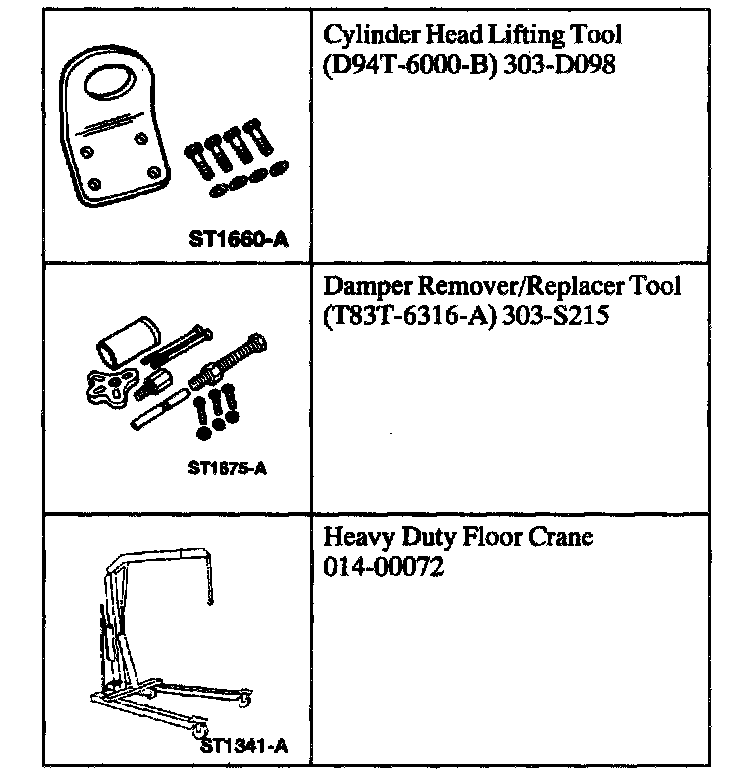
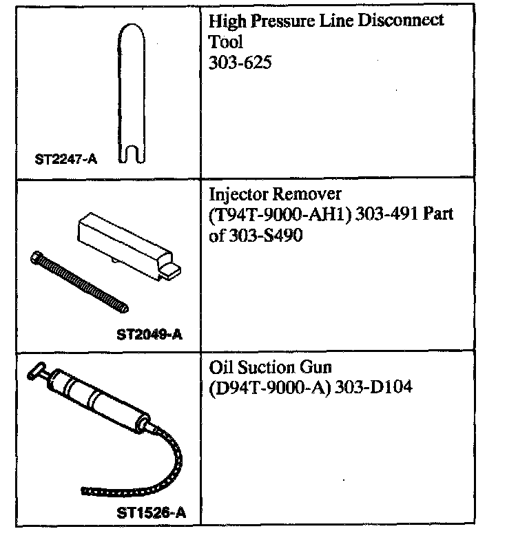
Special Tool(s)
Vehicles with air conditioning
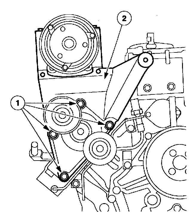
1. Remove the A/C compressor mounting bracket.
1. Remove the mounting bolts.
2. Remove the mounting bracket.
All vehicles
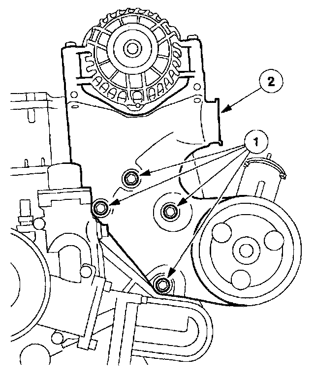
2. Remove the generator mounting bracket.
1. Remove the mounting bolts.
2. Remove the mounting bracket.
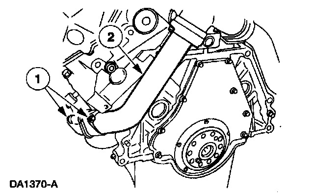
3. Remove the exhaust adapter pipes.
1. Remove the four mounting bolts and nuts.
2. Remove the exhaust adapter pipes.
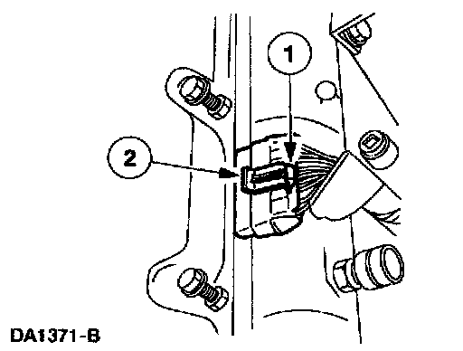
4. Disconnect the fuel injector/glow plug nine pin connectors.
1. Disconnect the retaining clip.
2. Disconnect the nine pin connector.
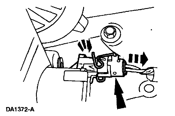
5. Disconnect the exhaust back pressure solenoid electrical connector.
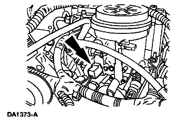
6. Disconnect the fuel heater/water sensor electrical connector.
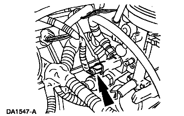
7. Disconnect the injection pressure regulator electrical connector.
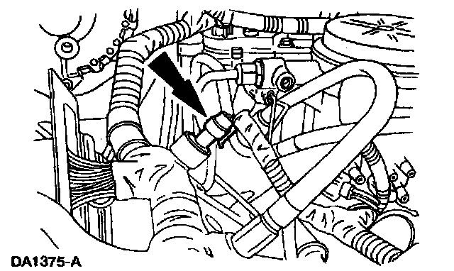
8. Disconnect the injection oil pressure sensor electrical connector.
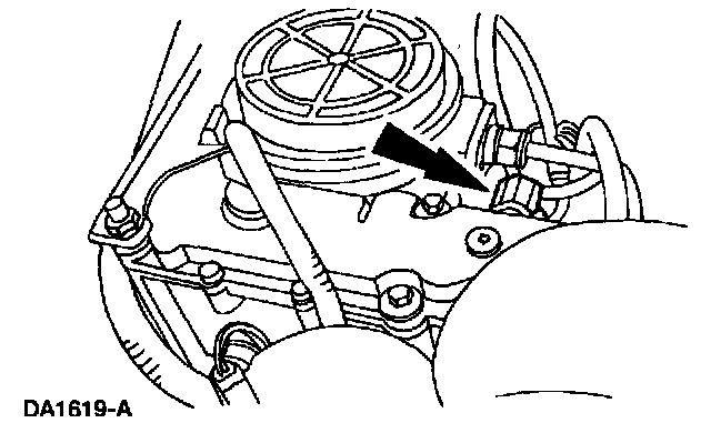
9. Disconnect the engine oil temperature sensor electrical connector.
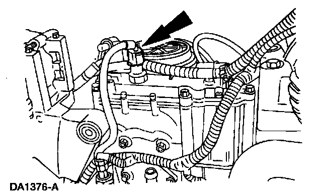
10. Disconnect the engine oil pressure sensor electrical connector.
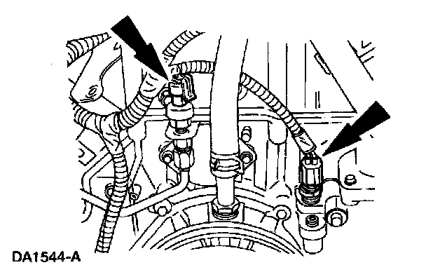
11. Disconnect the exhaust back pressure sensor and Engine Coolant Temperature (ECT) sensor electrical connector.
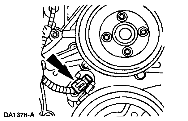
12. Disconnect the Camshaft Position (CMP) sensor electrical connector.
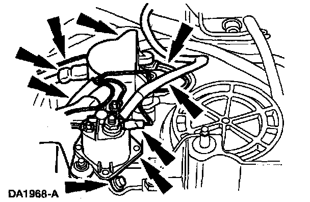
13. Remove the cover. Label and disconnect the electrical leads. Remove the two nuts and the glow plug relay/intake air heater relay and bracket as an assembly.
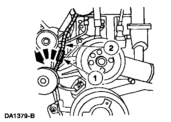
14. Remove the engine electrical harness.
1. Disconnect the pushpin retainer.
2. Remove the engine harness.
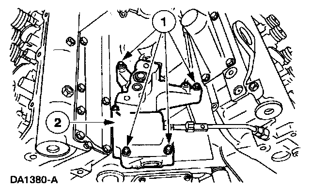
15. Remove the turbocharger pedestal.
1. Remove the bolts.
2. Remove the pedestal.
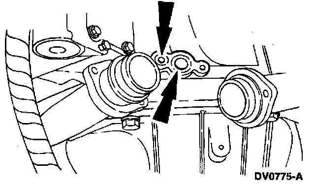
16. Remove and discard the two O-ring seals.
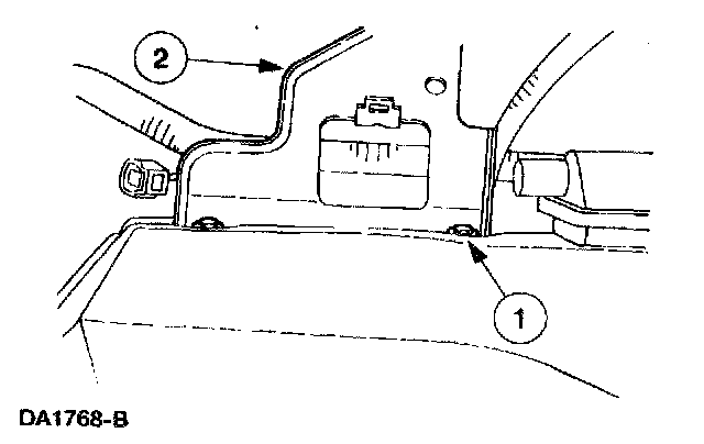
17. Remove the air inlet duct tube mounting bracket.
1. Remove the nuts.
2. Remove the bracket.
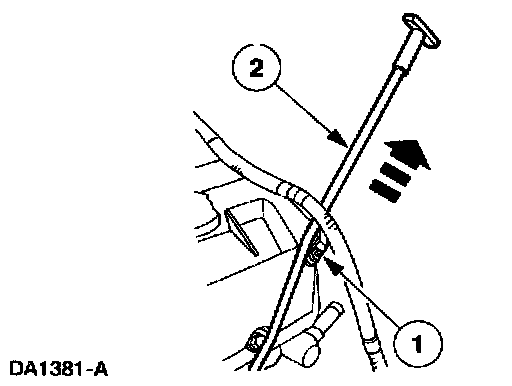
18. Remove the oil level indicator tube.
1. Remove the nut.
2. Pull upward and remove the oil level indicator tube.
19. NOTE: Both the left side and the right side valve covers are removed the same way. Only the right side valve cover is shown.
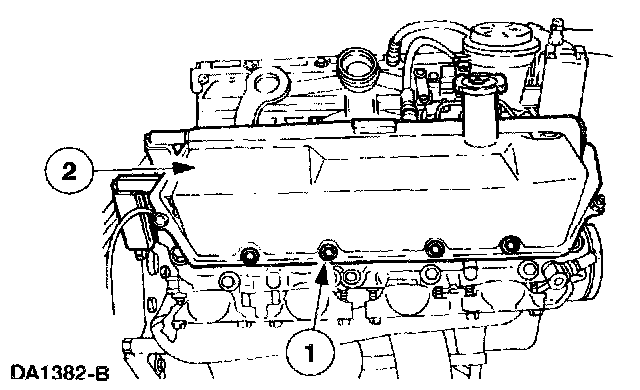
Remove the valve covers.
1. Remove the mounting bolts.
2. Remove the valve cover.
20. NOTE: Both the left side and the right side valve cover gaskets are removed the same way. Only the right side valve cover gasket is shown.
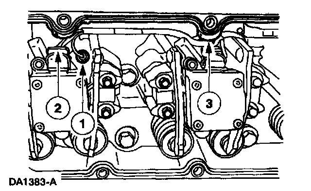
Remove the valve cover gaskets.
1. Disconnect the four fuel injector electrical connectors.
2. Disconnect the four glow plug electrical connectors.
3. Remove the valve cover gasket.
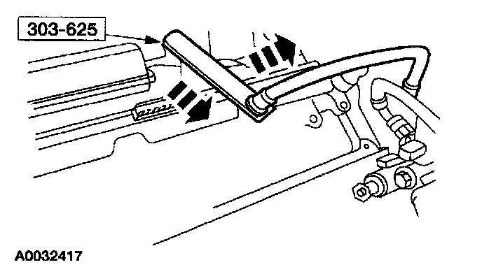
21. Using the special tool, remove the two high pressure oil hoses.
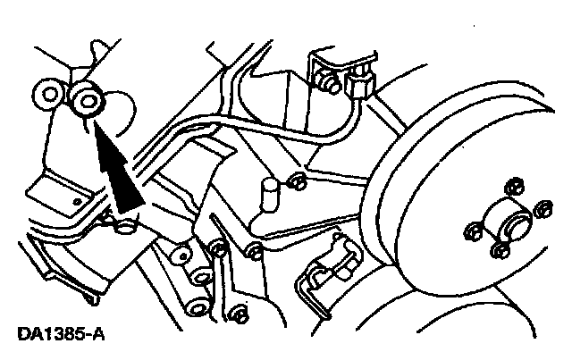
22. Drain the fuel galleries in the cylinder heads.
^ Loosen the fuel gallery plug and drain the fuel.
^ After the fuel has drained, tighten the fuel gallery plug.
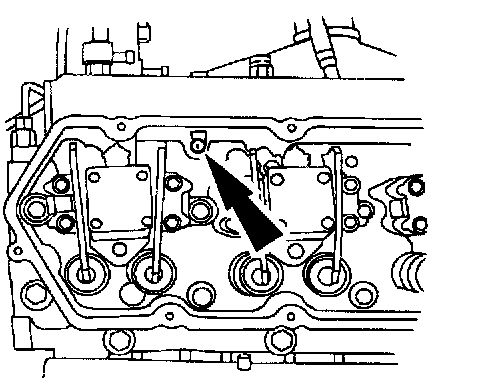
23. Drain the cylinder head oil galleries.
^ Remove the two oil gallery plugs.
^ After the oil has drained, tighten the oil gallery plugs.
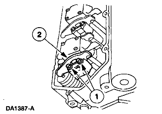
24. Remove the rocker arms.
1. Remove the bolts.
2. Remove the rocker arms and the push rods.
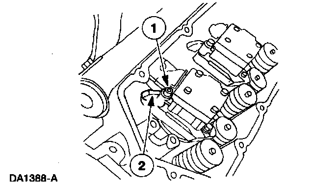
25. Remove the oil deflectors.
1. Remove the bolt.
2. Remove the oil deflector.
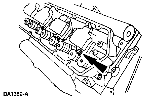
26. Remove the four fuel injector hold-down mounting bolts.
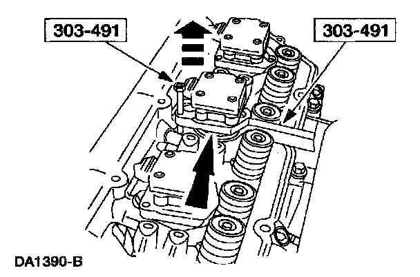
27. Using the special tool, remove the four fuel injectors.
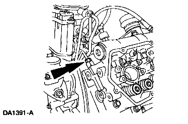
28. Remove the two fuel tubes from the cylinder heads.
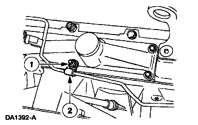
29. Remove the fuel tube and clamp.
1. Remove the nut.
2. Remove the fuel line and clamp from the stud bolt.
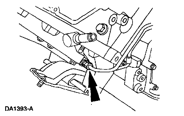
30. Disconnect the exhaust back pressure tube.
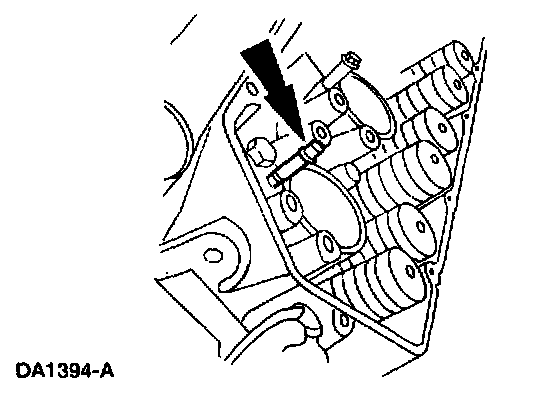
31. Remove the fuel injector hold-down bolts.
32. Remove the glow plugs.
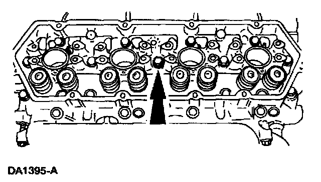
33. Remove the 18 cylinder head bolts.
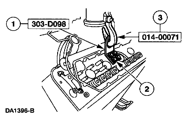
34. Remove the cylinder heads.
1. Position the special tool.
2. Install the four bolts.
3. Attach the special tool and remove the cylinder head.
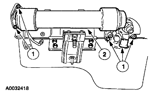
35. Remove the oil cooler.
1. Remove the bolts.
2. Remove the oil cooler and the gaskets.
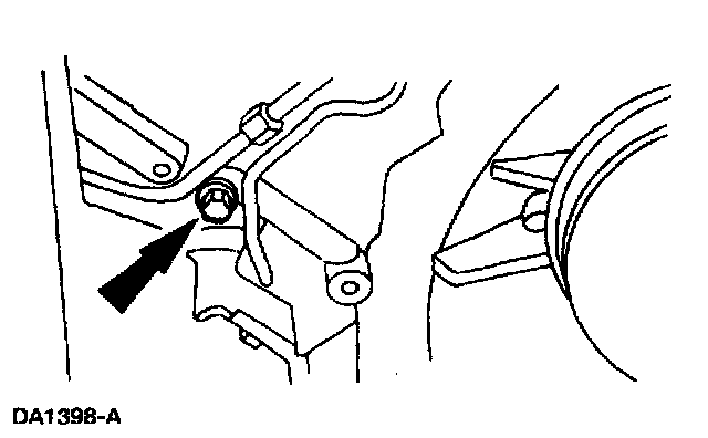
36. Remove the bolt from the fuel drain tube retainer clamp.
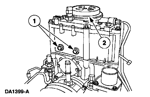
37. Remove the fuel filter/water separator assembly.
1. Remove the bolts.
2. Remove the fuel filter/water separator assembly.
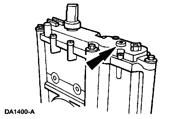
38. Remove the plug and, using special tool 303-D104 (D94T-9000-A), draw the oil from the reservoir.
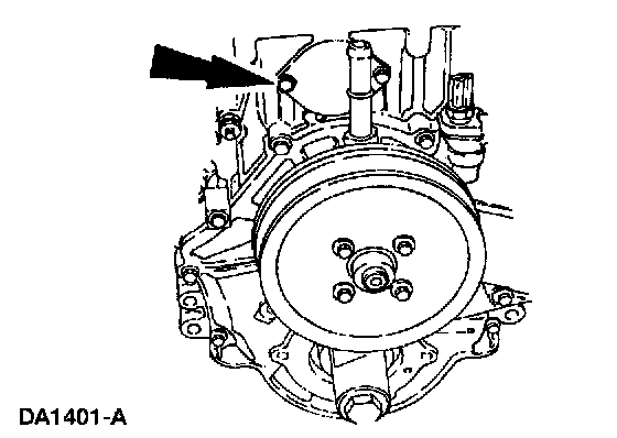
39. Remove the bolts and the access cover.
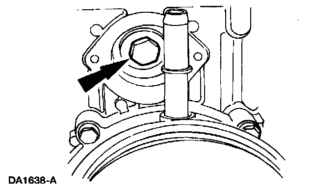
40. Remove the high pressure oil pump drive gear retaining bolt and washer.
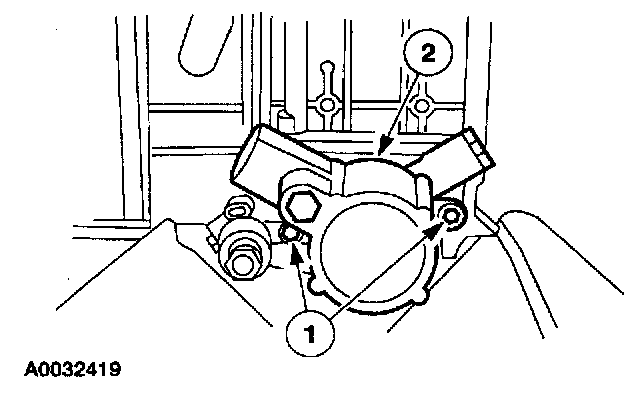
41. Remove the high pressure oil pump.
1. Remove the bolts.
2. Remove the high pressure oil pump and the gasket.
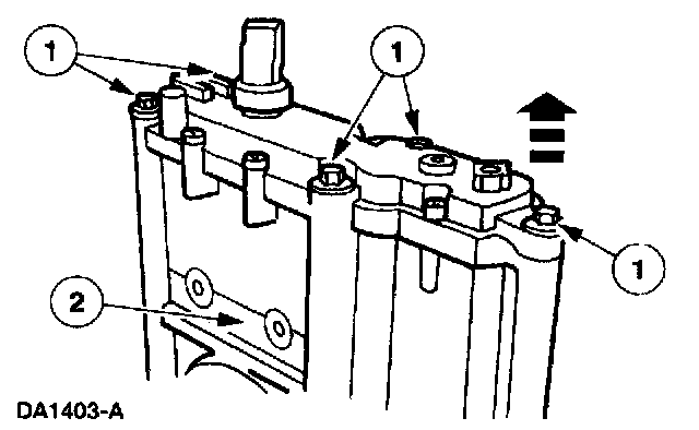
42. Remove the high pressure oil pump reservoir.
1. Remove the bolts.
2. Remove the reservoir and the gasket. Remove the high pressure oil pump drive gear.
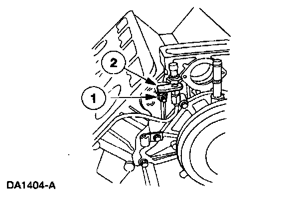
43. Remove the exhaust back pressure sensor and tube.
1. Remove the nut.
2. Remove the sensor and tube.
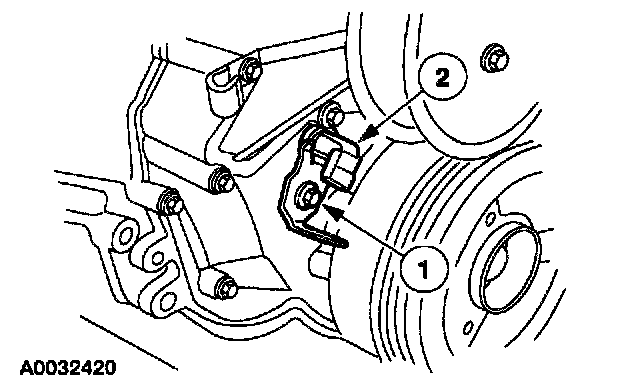
44. Remove the Camshaft Position (CMP) sensor.
1. Remove the bolt. Remove the Camshaft Position (CMP) sensor.
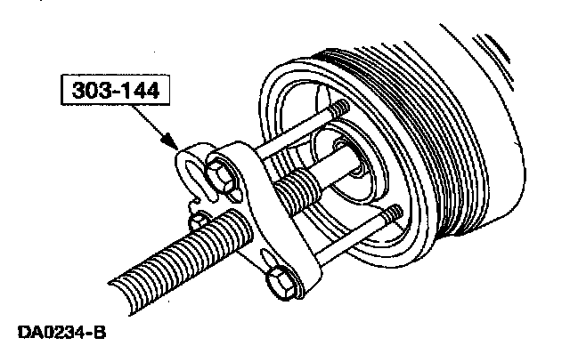
45. Remove the bolt. Using the special tool, remove the crankshaft vibration damper.
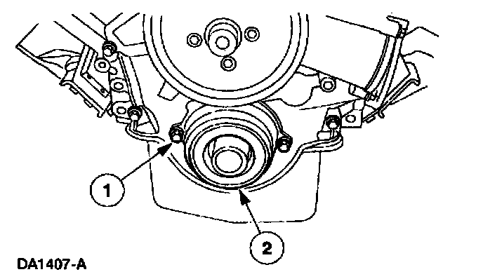
46. Remove the oil pump.
1. Remove the bolts.
2. Remove the oil pump housing and the O-ring seal.
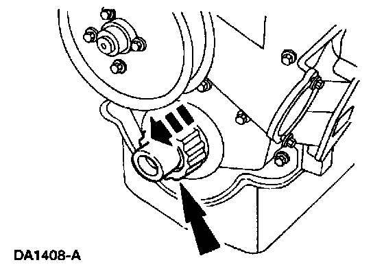
47. Remove the inner gerotor gear.
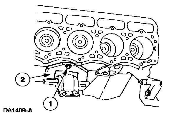
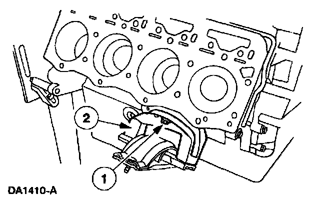
48. Remove the engine mounts.
1. Remove the three bolts.
2. Remove the mounts.
49. Drain the engine oil pan.
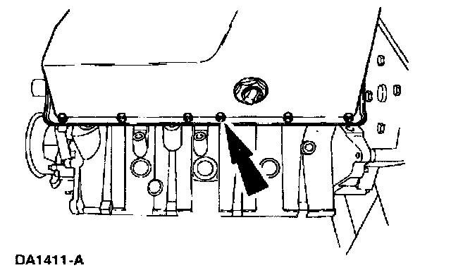
50. Remove the oil pan bolts.
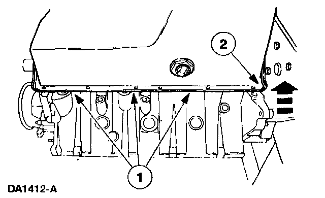
51. Remove the oil pan.
1. Cut the oil pan sealant all the way around the oil pan.
2. Carefully pry the oil pan up and away from the engine block.
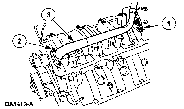
52. Remove the oil pickup tube.
1. Remove the nut.
2. Remove the two bolts.
3. Remove the pickup tube and gasket.
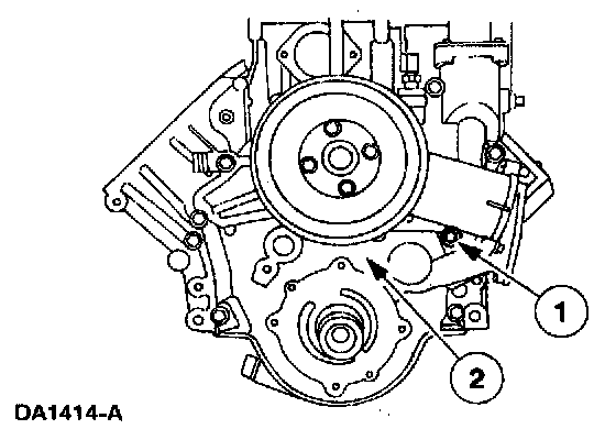
53. Remove the engine front cover.
1. Remove the bolts.
2. Remove the engine front cover and the gaskets.
54. CAUTION: Do not bend the engine rear cover. If the rear cover is bent, it will not reseal causing engine oil leaks.
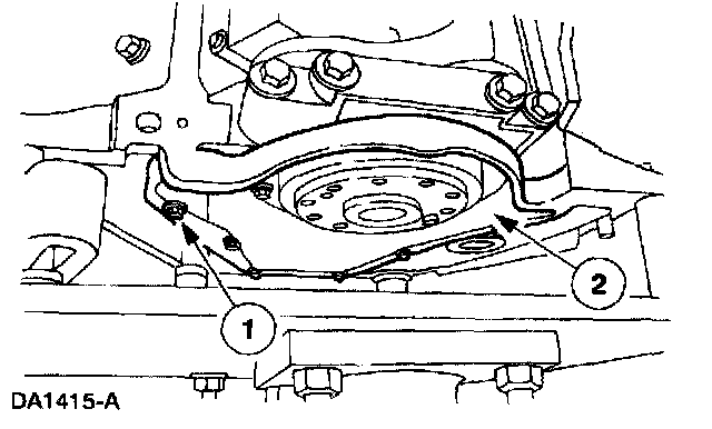
Remove the engine rear cover.
1. Remove the bolts.
2. Using a putty knife, carefully cut the sealant between the engine rear cover and the engine. Remove the cover.
55. NOTE: All sixteen lifters are removed the same way. Only two lifters are shown.
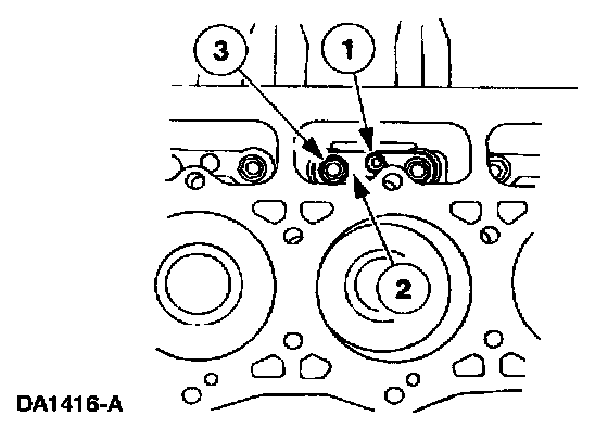
Remove the lifters.
1. Remove the bolt.
2. Remove the lifter retainer.
3. Remove the lifters.
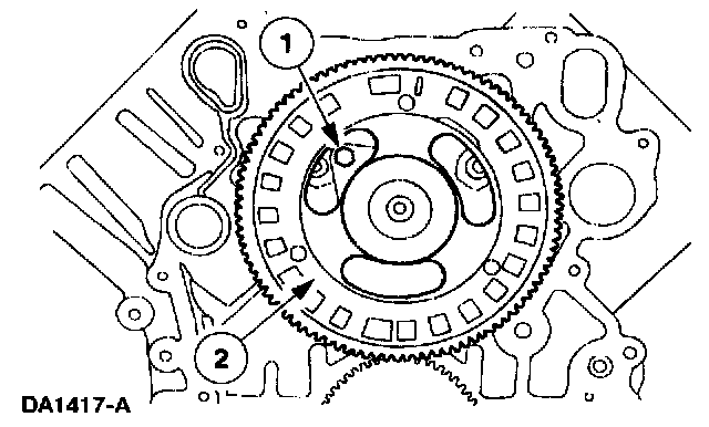
56. Remove the camshaft.
1. Remove the two retainer bolts.
2. Remove the camshaft and the drive gear.
57. Remove the carbon ridge from the top of the cylinder bores.
58. NOTE:
^ Mark and record all eight piston rods to make sure that they are installed into their correct cylinder bores during assembly.
^ All eight pistons and rod assemblies are removed the same way. Only one piston and rod assembly is shown.
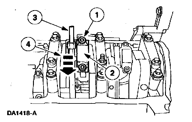
Remove the piston and rod assemblies.
1. Remove the nuts.
2. Remove the rod cap and bearing half.
3. Install the rod bolt protector sleeves.
4. Push the rod and piston assembly down and out of the engine block.
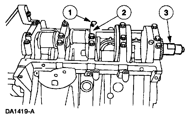
59. Remove the crankshaft.
1. Remove the bolts.
2. Remove the main bearing caps and the bearing halves.
3. Using a suitable sling and special tool 014-00071, remove the crankshaft.
60. NOTE: All eight piston oil cooling jets are removed the same way. Only one jet is shown.
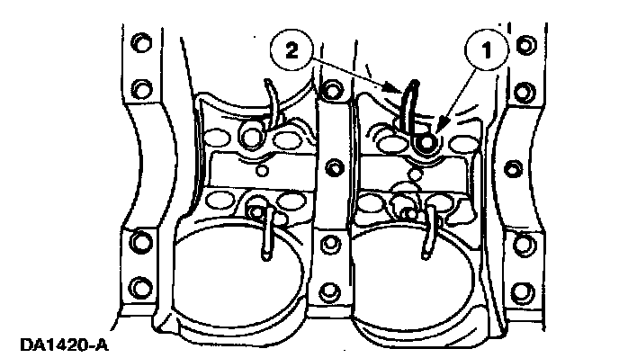
Remove the piston oil cooling jets.
1. Remove the bolt.
2. Remove the cooling jet.
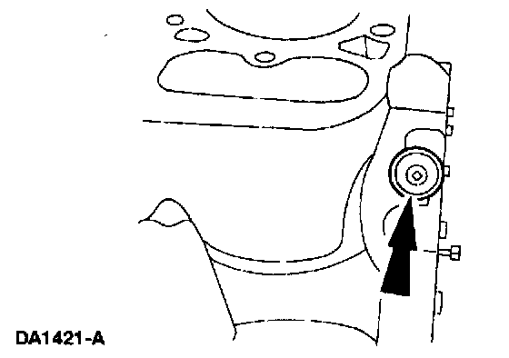
61. Remove the anti-drainback check ball retainer cap.
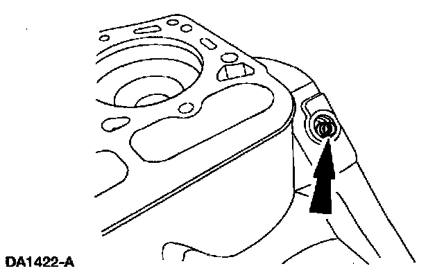
62. Remove the spring.
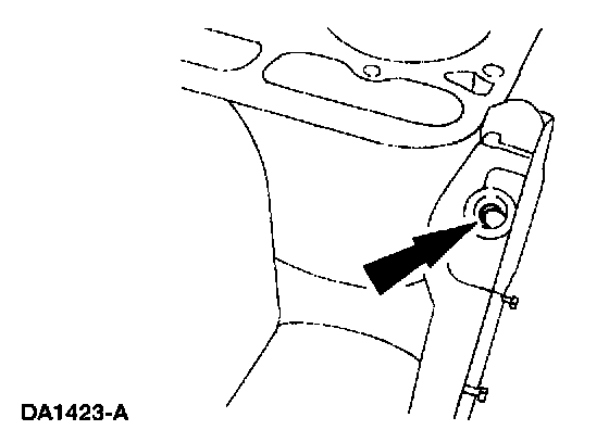
63. Remove the anti-drainback check ball.