Part 2
Item 48: Camshaft Roller Followers Assembly NoteNOTE: Be sure to install the roller followers in their original locations.
1. Position the piston of the cylinder in which the roller followers are being installed at the bottom of the stroke and camshaft lobe at the base circle.
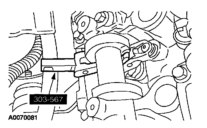
2. Using the special tool, compress the valve spring and install the roller follower.
3. Repeat the above steps to install all the roller followers.
Item 52: Engine Front Cover Assembly Note
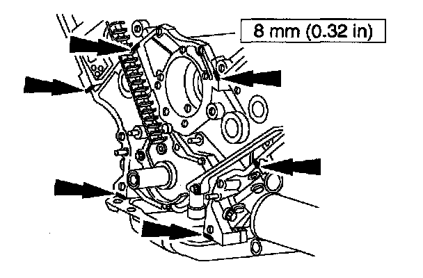
1. NOTE: If the engine front cover is not secured within four minutes, the sealant must be removed and the sealing area cleaned with metal surface cleaner. Allow to dry until there is no sign of wetness, or four minutes, whichever is longer. Failure to follow this procedure can result in future oil leakage.
Apply silicone gasket and sealant in the locations shown.
Part 1 Of 2:
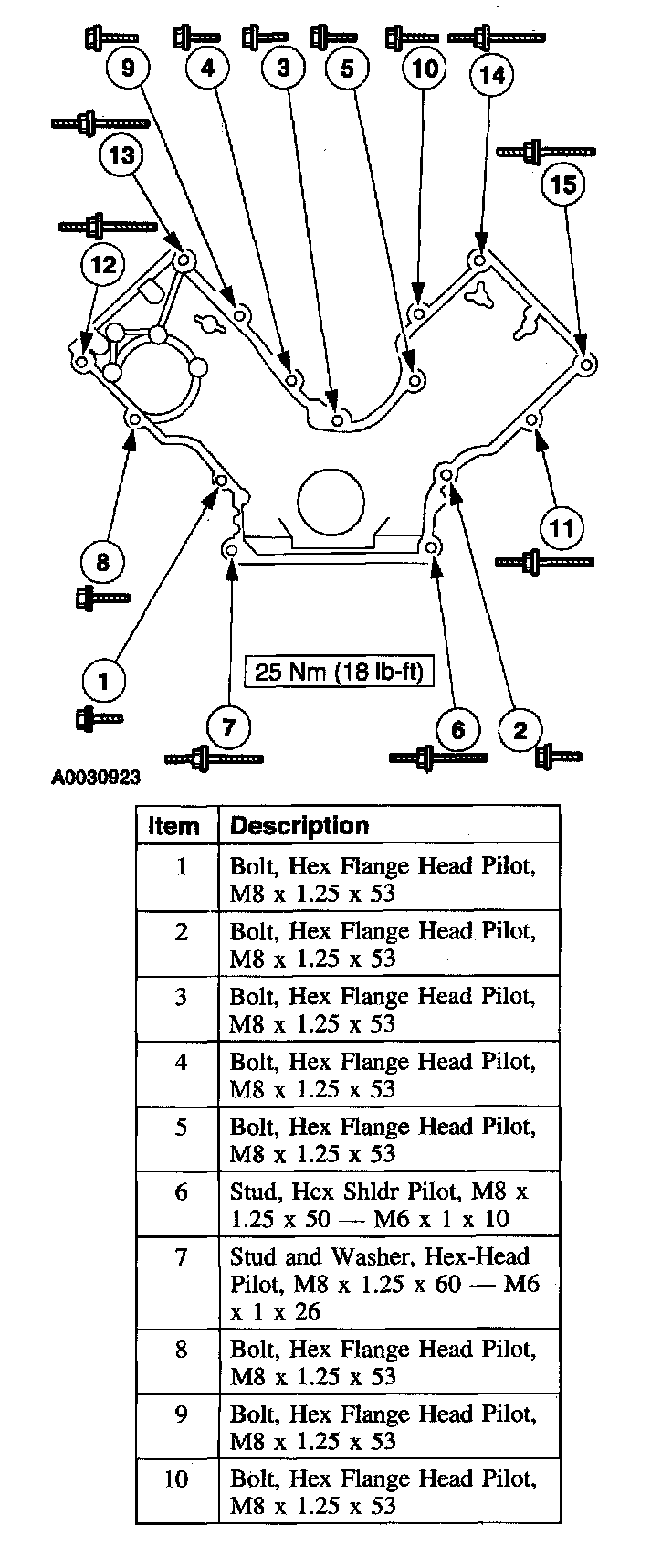
Part 2 Of 2:
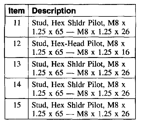
2. Install the engine front cover.
Item 61: Oil Pan Assembly Note
NOTE: If the oil pan is not secured within four minutes, the sealant must be removed and the sealing areas cleaned with metal surface cleaner. Failure to follow this procedure can cause future oil leakage.
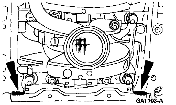
1. Apply silicone gasket and sealant in two places.
2. Apply silicone gasket and sealant in two places.
Item 62: Oil Pan Bolts Assembly Note
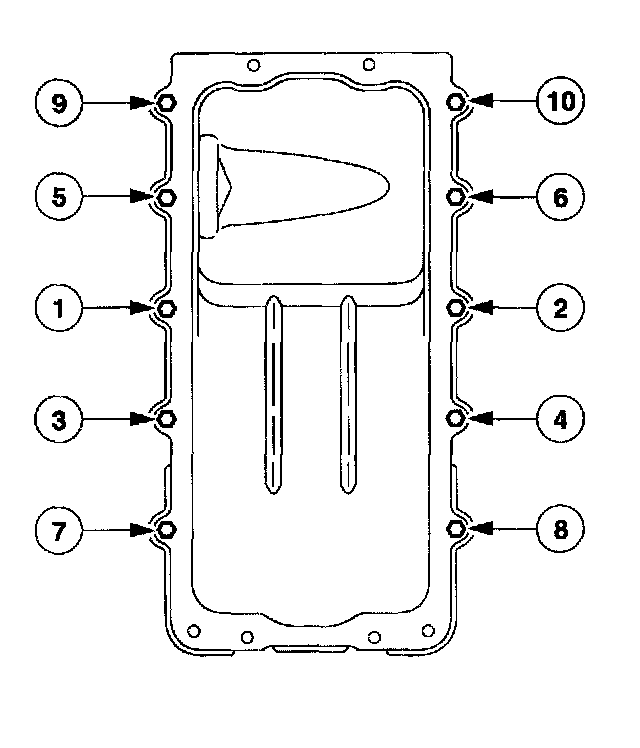
1. Tighten the bolts in the sequence shown.
^ Tighten to 20 Nm (15 ft. lbs.).
^ Rotate an additional 60 degrees.
Items 64 - 66 and 68 - 70: Valve Rocker Arm Cover Assembly Note
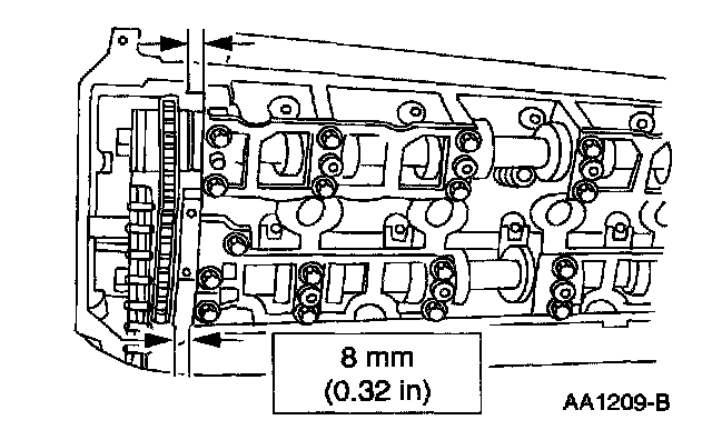
1. NOTE: If the valve cover is not secured within four minutes, the sealant must be removed and the sealing area cleaned with metal surface cleaner. Allow to dry until there is no sign of wetness, or four minutes, whichever is longer. Failure to follow this procedure can result in future oil leakage.
Apply silicone gasket and sealant in the locations shown.
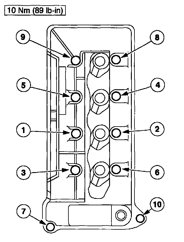
2. NOTE: The RH is shown; the LH is similar.
Install the valve rocker arm covers and tighten the bolts in the sequence shown.
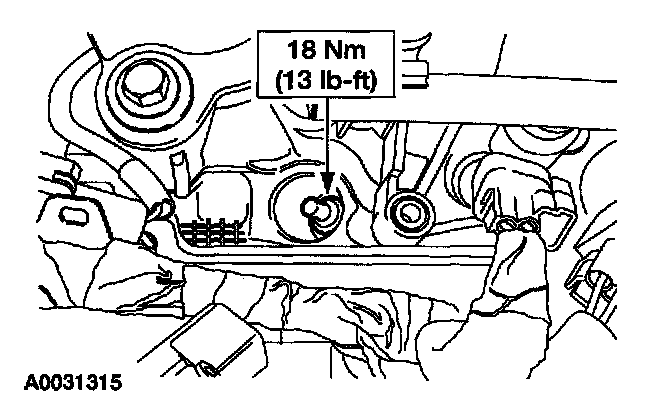
3. Install the spark plugs.
Item 71: RH Engine Support Insulator Bracket Assembly Note
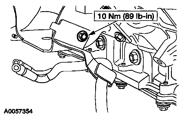
1. Install the bracket and the bolt.
Item 85: LH Exhaust Manifold Nuts Assembly Note
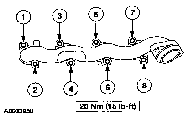
1. Install the LH exhaust manifold and tighten the nuts in the sequence shown.
Item 93: RH Exhaust Manifold Nuts Assembly Note
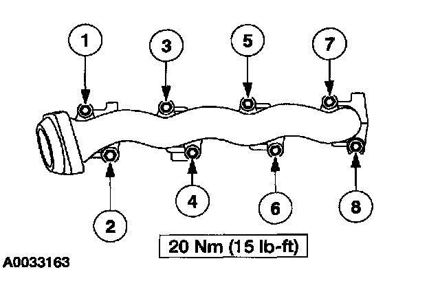
1. Install the RH exhaust manifold and tighten the nuts in the sequence shown.
Item 98: Intake Manifold Bolts Assembly Note
1. Hand - start all fasteners.
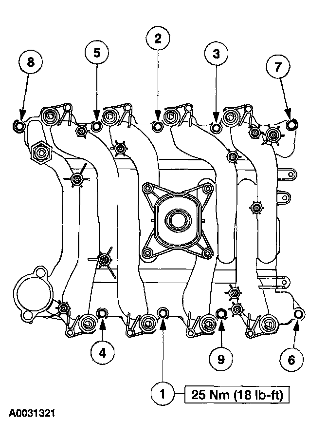
2. Tighten all fasteners in the sequence shown.
Item 112: Water Pump Assembly Note
1. CAUTION: Do not rotate the water pump housing once the water pump has been positioned in the cylinder block. Damage to the O - ring seal will occur.
Lubricate the O - ring seal before installing the water pump.
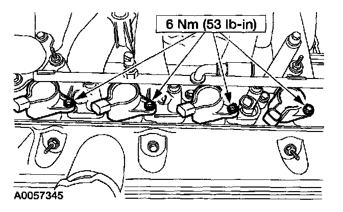
Item 114: Ignition Coil Assembly Note
1. Apply dielectric compound to the inside of the ignition coil boots.
Item 116: Engine Wiring Harness Assembly Note
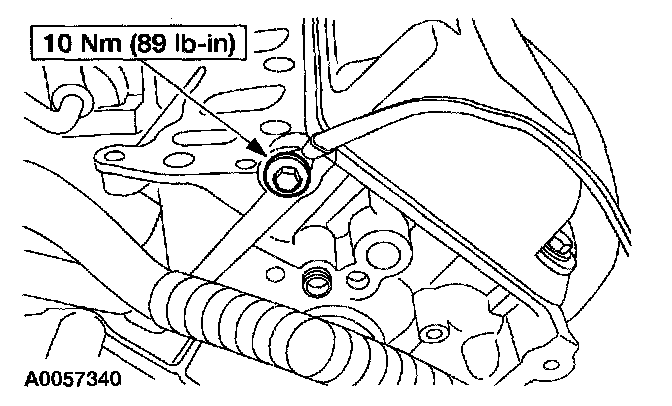
1. Install the ground wire and bolt.
2. Position the engine wiring harness onto the engine and connect the harness locators.
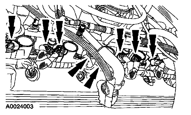
3. Connect the eight fuel injector and ignition coil electrical connectors.
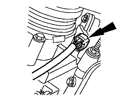
4. Connect the CKP sensor electrical connector.
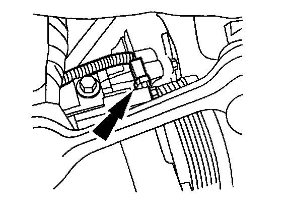
5. Connect the A/C compressor electrical connector.
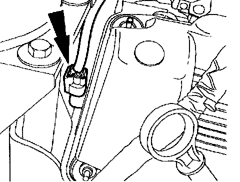
6. Connect the CMP sensor electrical connector.
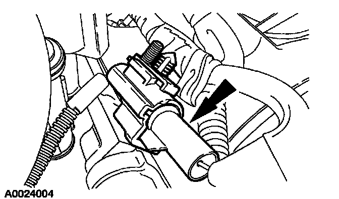
7. Connect the Cylinder Head Temperature (CHT) sensor electrical connector.
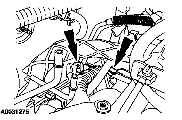
8. Connect the KS electrical connector and the wiring harness pin - type retainer.
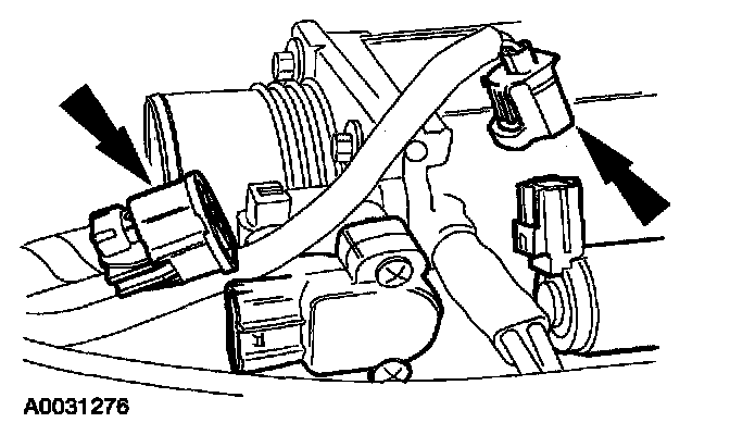
9. Connect the Throttle Position (TP) sensor and the Idle Air Control (IAC) valve electrical connectors.
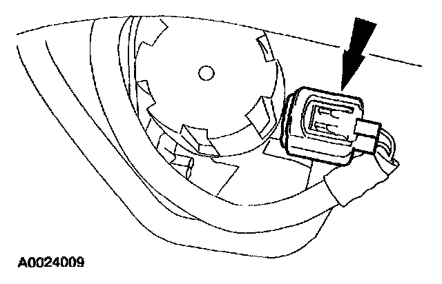
10. Connect the EGR vacuum regulator solenoid electrical connector.
Item 117: Vacuum Harness Assembly Note
1. Position the vacuum hose harness in place.
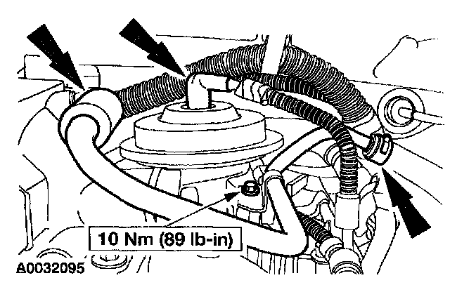
2. Connect the brake booster vacuum hose and install the bolt.
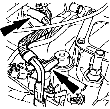
3. Connect the vacuum hoses to the throttle body adapter and the fuel pressure regulator.
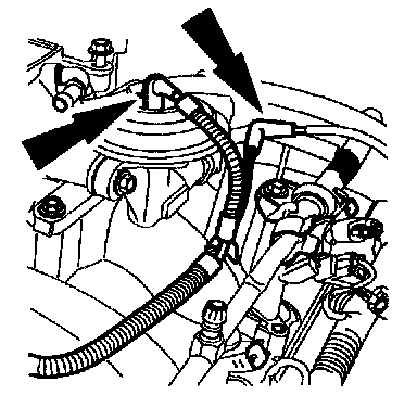
4. Connect the vacuum hoses to the EGR valve and the EVAP canister purge solenoid.
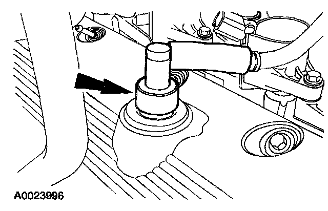
5. Install the Positive Crankcase Ventilation (PCV) valve and tube.
Item 122: Power Steering Pressure Hose O - Ring Seal Assembly Note
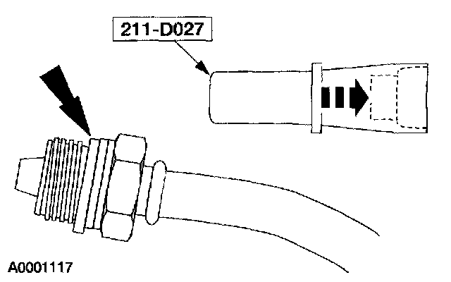
1. Using the appropriate special tool, install a new O - ring seal on the power steering pressure hose fitting.
Item 124: Power Steering Pump Pulley Assembly Note
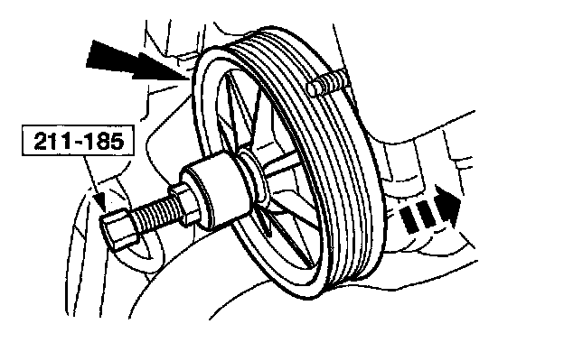
1. Using the special tool, install the power steering pump pulley.
Item 129: Generator Support Bracket Assembly Note
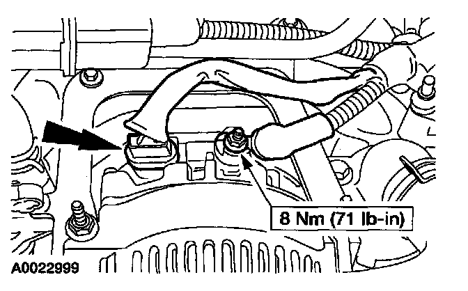
1. Connect the generator electrical connectors.
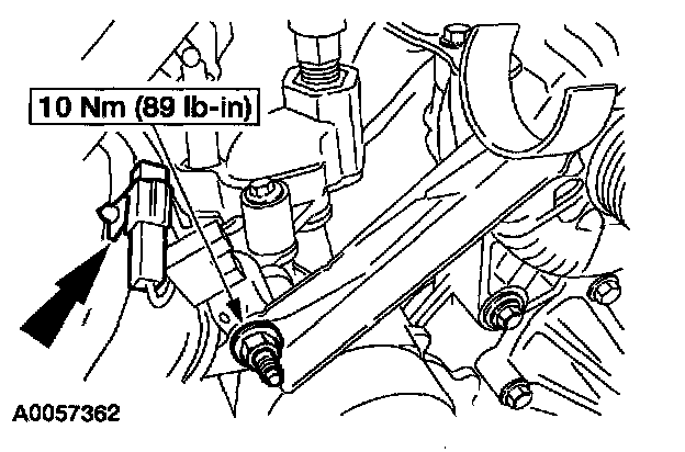
2. Install the upper radiator hose bracket and the radio capacitor.
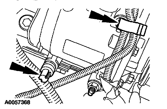
3. Position the harness and connect the retainers.
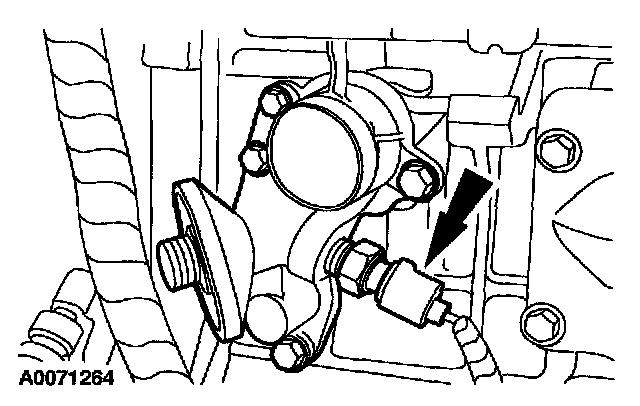
4. Install the oil pressure switch electrical connector.
Item 135: Crankshaft Front Seal Assembly Note
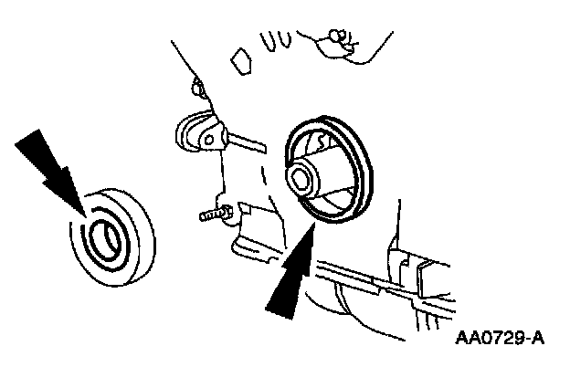
1. Lubricate the front oil seal and the engine front cover with clean engine oil.
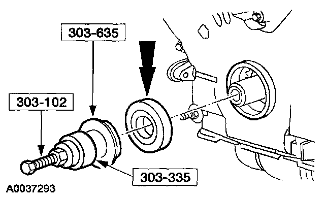
2. Using the special tools, install the front oil seal.
Items 136 - 138: Crankshaft Pulley Assembly Note
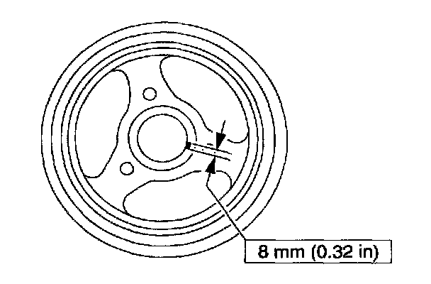
1. Apply silicone gasket and sealant to the Woodruff key on the crankshaft pulley.
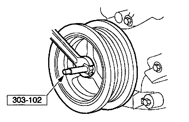
2. Using the special tool, install the crankshaft pulley.
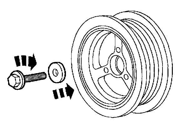
3. Install the crankshaft pulley and tighten the bolt in four stages:
^ Stage 1: Tighten to 90 Nm (66 ft. lbs.).
^ Stage 2: Loosen the bolt one full turn.
^ Stage 3: Tighten to 50 Nm (37 ft. lbs.).
^ Stage 4: Tighten an additional 90 degrees.
Items 153 and 154: Engine Lifting Bracket and Bolts Assembly Note
1. Install right side engine lifting bracket and bolts (not shown).
Item 155: Power Steering Reservoir Assembly Note
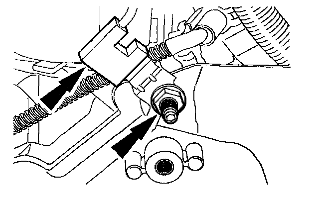
1. Install the power steering bracket and the radio interference capacitor and nut.
Item 160: Power Steering Cooler - to - Reservoir Hose Assembly Note
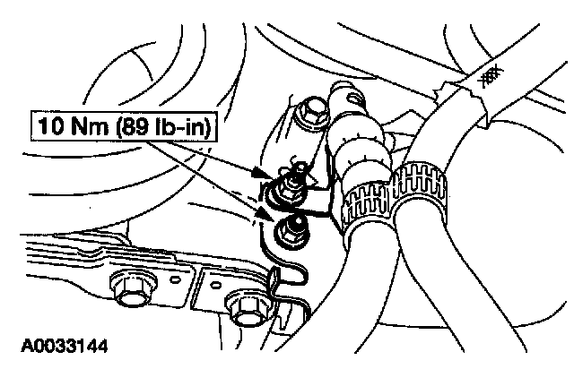
1. Install the power steering hose support bracket.
Items 165 and 166: Crankshaft Rear Seal Retainer Plate and Bolts Assembly Note
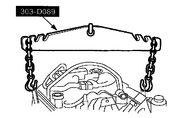
1. Using the special tool and a floor crane, remove the engine from the engine stand.
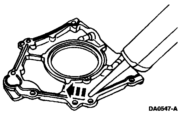
2. NOTE: If not secured within four minutes, the sealant must be removed and the sealing area cleaned with metal surface cleaner. Allow to dry until there is no sign of wetness, or four minutes, whichever is longer. Failure to follow this procedure can result in future oil leakage.
Apply a 4 mm (0.16 inch) bead of silicone gasket and sealant around the rear oil seal retainer plate sealing surface. Also apply a bead of silicone gasket and sealant at the junction where the cylinder block, oil pan and rear oil seal retainer plate meet.
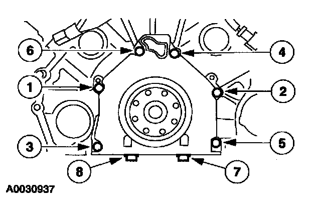
3. Install the rear oil seal retainer plate. Tighten the bolts in the sequence shown.
^ Tighten bolts 1 - 6 to 10 Nm (89 inch lbs.).
^ Hand - tighten bolts 7 and 8.
^ Tighten bolts 7 and 8 to 20 Nm (15 ft. lbs.).
^ Tighten bolts 7 and 8 an additional 60 degrees.
Item 168: Crankshaft Rear Seal Assembly Note
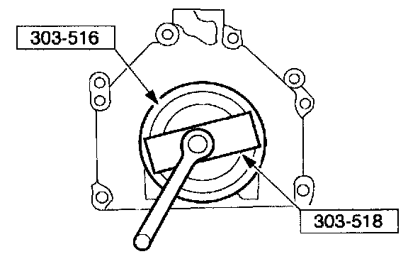
1. Using the special tools, install the crankshaft rear main seal.
Item 169: Crankshaft Oil Slinger Assembly Note
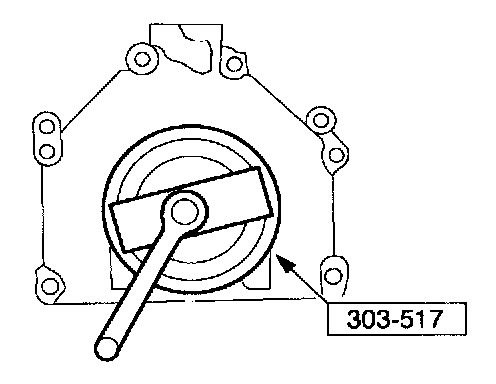
1. Using the special tool, install the crankshaft oil slinger.
Item 172: Flexplate Bolts Assembly Note
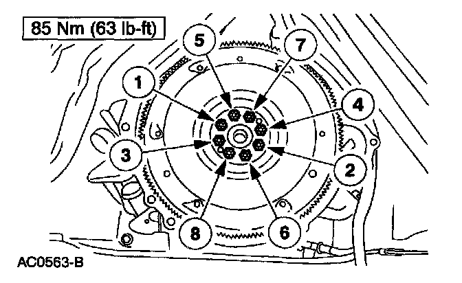
1. Install the flywheel bolts in the sequence shown.