Electro Drive Engine Cooling Fan - Service Revision
Article No. FAN - ELECTRO - DRIVE ENGINE COOLING -
87-7-4 2.3L OHC TURBO - NEW SHOP MANUAL SERVICE PROCEDURE
FORD: 1987 THUNDERBIRD
ISSUE: The 1987 Car Shop Manual, Volume D, Section 27-10 was not updated at the time of publication to reflect the service procedures for the 1987 Thunderbird turbo electro-drive cooling fan.
ACTION: If service is required, use the service procedures on pages 13 through 15 of this TSB.
OTHER APPLICABLE ARTICLES: None
WARRANTY STATUS: "INFORMATION ONLY"
DESCRIPTION AND OPERATION
The electro-drive cooling fan system consists of two fans attached to a fan shroud that is located behind the radiator. Each fan is driven by a one-speed electric motor. The electrodrive cooling system is wired to operate only when the ignition switch is in the RUN position, thereby preventing cooling fan operation after the ignition switch is turned OFF.
WARNING: DISCONNECT THE COOLING FAN PRIOR TO PERFORMING ANY UNDERHOOD SERVICE SINCE THE FAN COULD CYCLE IF THE IGNITION SWITCH IS LEFT IN THE ON POSITION EVEN THOUGH THE ENGINE IS NOT RUNNING.
The cooling fans are controlled during vehicle operation by the integrated relay assembly and the EEC IV module which will energize the cooling fans under any of the following conditions:
4-Blade (Passenger Side) Fan
a. The engine temperature (measured by ECT sensor) is higher than normal (fan turns ON at 93~C (200~F) and OFF at 87~C (190~F)).
b. The A/C ON (compressor clutch is energized).
7-Blade (Driver Side) Fan
a. Engine temperature (measured by ECT sensor) is higher than normal (ON at 104.5~C (220~F), OFF at 99~C (210~F))
- AND - the 4-blade fan has been running for at least 10 seconds.
b. A/C head pressure is at 310 psi and OFF at 265 psi. This function is independent of the EEC IV system and engine block temperature.
Both Fans
Will be off when:
a. The engine coolant temperature is below the fan OFF temperature
- AND - the A/C clutch has been de-energized for more than 2 seconds (A/C demand switch turned OFF, high drive demand (WOT mode) or cycling pressure switch open).
REMOVAL AND INSTALLATION
Cooling Fan Controller Location
Thunderbird - Under instrument panel, between steering column and L.H. side cowl panel.
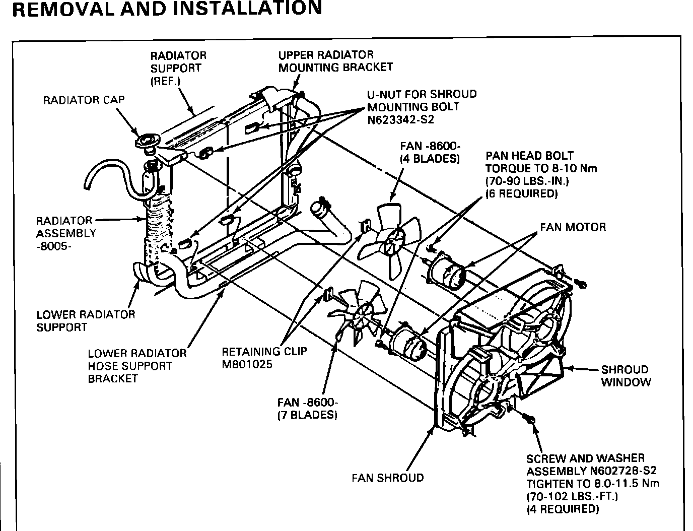
Fig. 3A - Cooling Fan Electric - Thunderbird:
Fan Motor - Removal
Refer to Fig. 3A
1. Disconnect battery ground cable.
2. Unplug the fan wiring harness attachment pin from the shroud. Disconnect the wiring harness from the fan motor connector (pull up on the single lock finger to separate the connectors).
3. Remove the four screws connecting the shroud assembly to the vehicle.
4. Lift the shroud and fan assembly from the vehicle.
5. Remove the retaining clip from the end of the shaft by pushing it until it snaps off.
6. Remove the fan from the motor.
NOTE: After the clip is removed, slight deburring of the shaft may be required to permit fan removal.
7. Remove the pan head bolts attaching the fan motor to the shroud.
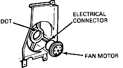
Fig. 3B - Electro-Drive Cooling Fan Motor Installation:
Fan Motor - Installation
1. Insert fan motor into shroud assembly by lining up the harness connector located at the back of the fan motor with the small dot next to the bolt hole on the shroud assembly. (Fig. 3B).
NOTE: It is essential that the motor be inserted into the shroud properly. If the electrical connector on the motor does not line up with the dot on the shroud assembly, the motor mounting holes will not be aligned with the holes in the shroud.
2. Install the three pan head screws. Torque to 70-102 in.lbs. (8.0-11.5 N-m).
3. Slip the fan onto the motor.
4. Install spring retainer on the fan by pushing it until it snaps into place.
5. Position the fan and shroud assembly into the vehicle.
6. Install the four screws that mount the shroud and fan assembly to the vehicle (install the two upper mounting screws first).
7. Connect the motor wiring connector to the wiring harness and secure the connector pin to shroud.
8. Connect battery ground cable and check the fans for proper operation.
DIAGNOSIS
Cooling fans are controlled by the Integrated Controller and the EEC IV system. See Pinpoint Test "X" in the 1987 Engine/Emission Diagnosis Shop Manual.
SPECIFICATIONS
TORQUE SPECIFICATION
Description N-m In.Lbs.
Fan Motor to Fan Shroud Bolt 8.0-10.0 70-90
Fan Shroud to Radiator 8.0-11.5 70-102