(2)Transmission End Play Check
A rear end play check is necessary to properly reassemble the rear portion of the A4LD automatic overdrive transmission.
This end play check determines:
^ The amount of space existing between the thrust washer surfaces of the overdrive center support (7A130) and the intermediate brake drum (7D044), and
^ The thickness of the No. 4 thrust washer (7D014) required to obtain an end play of .30- .54 mm (.012-.022 inch).
Figure 14:
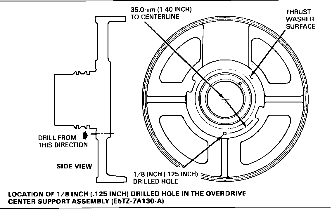
To perform this end play check, it will be necessary to fabricate a depth gauge fixture from a service replacement overdrive center support assembly (E5TZ-7A130-A). A 1/8 inch (.125") hole must be drilled through the thrust washer surface of the center support (see Figure 14 for location of the hole) to allow access to the area between the thrust surfaces of the support and the intermediate brake drum with depth micrometer (D80P-4201-A). Additionally, the rubber seals must be removed from the support to allow easy insertion into the intermediate brake drum.
The end play check must be performed during transmission assembly, right after installation of the intermediate band, apply strut and anchor strut.
Figure 15:
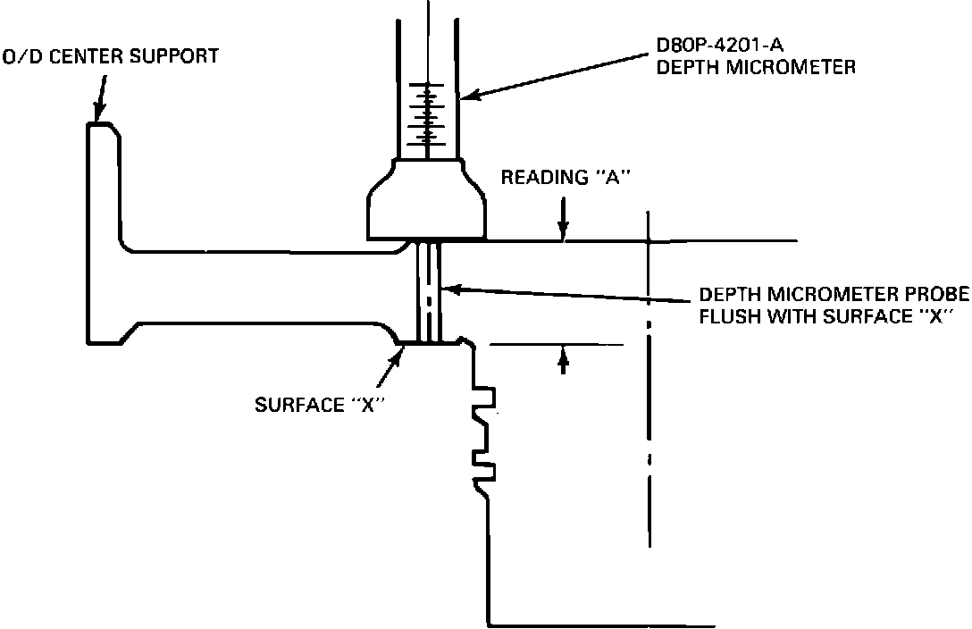
1. Place the depth micrometer (D80P-4201-A) over the drilled hole in the fabricated depth gauge fixture. Extend the probe until it is flush with the thrust washer surface of the fixture (Surface X, Figure 15). Record the reading appearing on the micrometer (Reading A).
Figure 16:
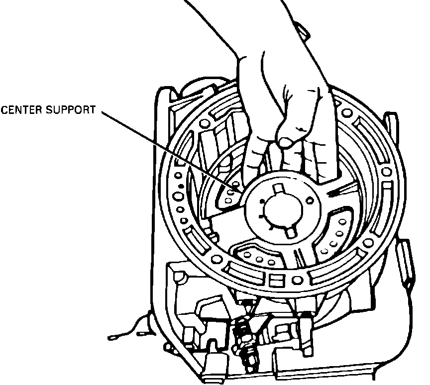
2. Install the fabricated depth gauge fixture into the intermediate brake drum and fully seat it in the transmission case. The fixture axially locates the drum in its proper position (Figure 16).
Figure 17:
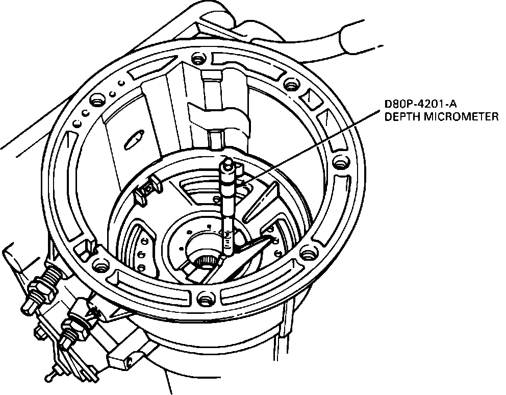
3. Place the depth micrometer over the drilled hole in the fixture (Figure 17).
Figure 18:
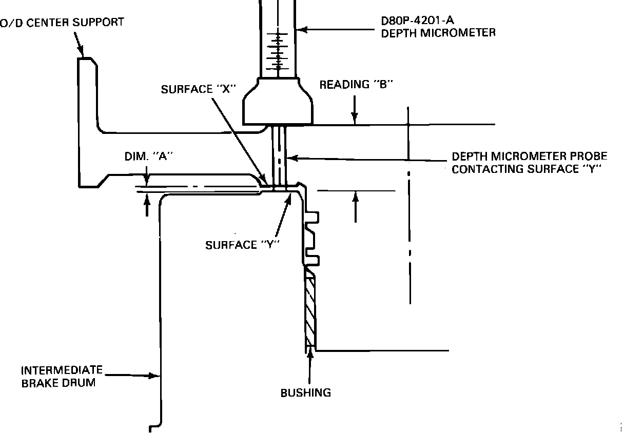
4. Continue extending the probe and record the reading (Reading B) appearing on the micrometer when the probe contacts the thrust washer surface of the intermediate brake drum (Surface Y, Figure 18).
5. Subtract Reading A from Reading B. The difference between these readings is Dimension A (space between thrust surfaces) (Figure 18).
6. Remove and rotate the fixture 180~ and repeat Steps 1 through 5.
7. Average the two Dimensions A.
8. Locate this dimension in the following chart and select the proper thrust washer required to obtain the specified end play of .30-.54 mm (.012-.022 inch).
Use Thrust Thrust Thrust
Washer Washer Washer Part
Dimension A I.D. No. Thickness No. (7D014)
.067-.074" 1 .053-.055" E5TZ-A
.075-.082" 2 .061-.063" E5TZ-B
.083-.090" 3 .069-.071" E5TZ-C
.091-.098" 4 .077-.079" E5TZ-D
.099-.106" 5 .085-.087" E5TZ-E
Dimension A, outside the above limits, indicate improper assembly, missing part or parts out of specification and require a rebuild of the unit.
9. Remove the fabricated depth gauge fixture (and retain for future use), install the correct thrust washer, and complete the reassembly (using a standard overdrive center support assembly in place of the fabricated depth gauge fixture).
PART NUMBER PART NAME CLASS
E5TZ-7D014-A Thrust Washer R
E5TZ-7D014-B Thrust Washer R
E5TZ-7D014-C Thrust Washer R
E5TZ-7D014-D Thrust Washer R
E5TZ-7D014-E Thrust Washer R
E5TZ-7A130-A Overdrive Center Support B