Service Procedure
WARNINGDO NOT SMOKE OR CARRY LIGHTED TOBACCO OR OPEN FLAME OF ANY TYPE WHEN WORKING ON OR NEAR ANY FUEL RELATED COMPONENTS. HIGHLY FLAMMABLE VAPORS ARE ALWAYS PRESENT AND MAY IGNITE. FAILURE TO FOLLOW THESE INSTRUCTIONS MAY RESULT IN PERSONAL INJURY.
WARNING
THIS PROCEDURE INVOLVES FUEL HANDLING. BE PREPARED FOR FUEL SPILLAGE AT ALL TIMES AND ALWAYS OBSERVE FUEL HANDLING PROCEDURES. FAILURE TO FOLLOW THESE INSTRUCTIONS MAY RESULT IN PERSONAL INJURY.
WARNING
THE FUEL SYSTEM REMAINS PRESSURIZED FOR A LONG TIME AFTER THE IGNITION IS SWITCHED OFF. THE INJECTOR PRESSURE MUST BE RELEASED BEFORE ATTEMPTING ANY REPAIRS. FAILURE TO FOLLOW THESE INSTRUCTIONS MAY RESULT IN PERSONAL INJURY.
1. Relieve the fuel system pressure by removing the fuel pump fuse from the battery junction box under the hood. Start the engine and allow it to idle1 then depress the accelerator pedal to stall the engine. Crank the engine for an additional 5 seconds to make sure the fuel supply manifold pressure has been relieved.
2. Install a memory saver, then disconnect the battery negative cable.
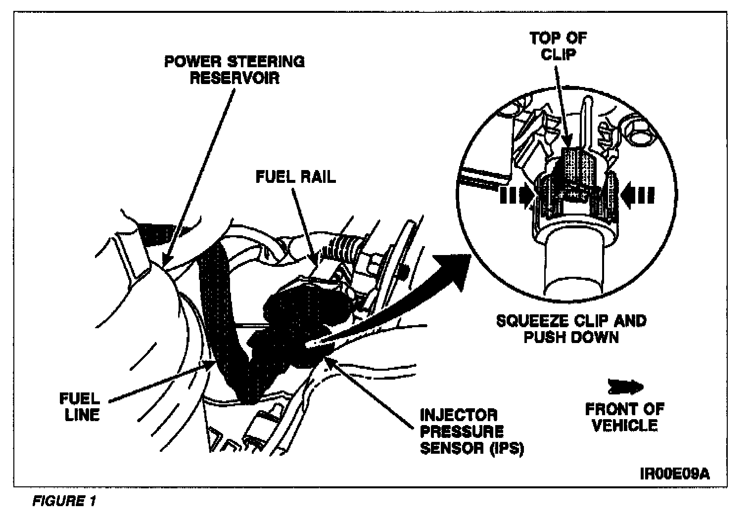
3. Disconnect the fuel line from the injector pressure sensor (IPS) as follows. See Figure 1.
^ Lift up on the top of the retaining clip.
^ Squeeze the sides of the clip inward and push down on the clip.
^ Pull the fuel line off the sensor.
4. Remove the two (2) retaining bolts from the IPS.
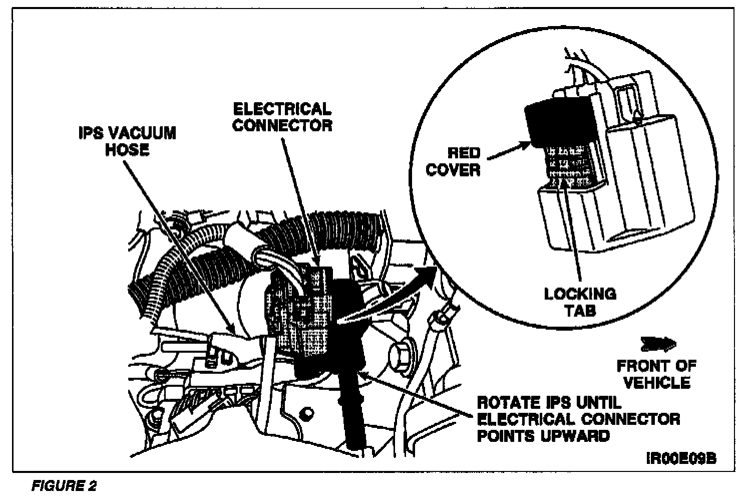
5. Rotate the IPS until the electrical connector is pointing upward, then pull the sensor out of the fuel rail. See Figure 2.
6. Disconnect the IPS electrical connector as follows. See Figure 2.
^ Slide the red cover up to expose the locking tab.
^ Depress the locking tab and slide the connector off the sensor.
7. Disconnect the vacuum hose, then remove and discard the IPS. See Figure 2.
8. Lubricate the 0-ring seal on the new IPS with clean engine oil to aid installation.
9. Connect the vacuum hose.
10. Slide the electrical connector onto the IPS. Then, slide the red cover over the locking tab.
11. Insert the new IPS into the fuel rail with the electrical connector pointing upward, then rotate to the installed position.
12. Install the two (2) retaining bolts. Tighten to 6 Nm (53 lb-in).
13. Connect the fuel line and secure the locking clip.
14. Install the fuel pump fuse into the battery junction box.
15. Connect the battery negative cable, then remove the memory saver.
16. Cycle the key to the ON position 2 to 3 times to pressurize the fuel system and check for leaks around the IPS.