With IB5/Manual Transaxle
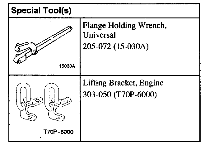
Special Tools:
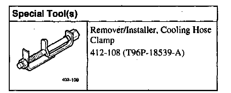
Special Tools
Removal
1. CAUTION: To prevent the risk of scalding, place a thick cloth over the filler cap before opening the cooling circuit. Failure to do so may result in personal injury.
Open the coolant expansion tank.
2. Remove the battery.
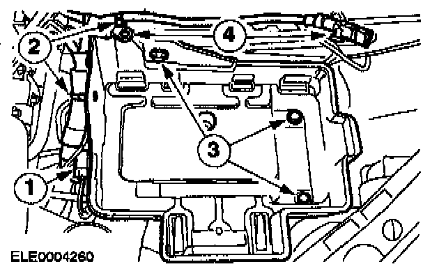
3. Remove the battery tray and the ground cable.
1. Unclip and separate the connector.
2. Unclip the wiring harness.
3. Unscrew the bolts.
4. Remove the positive and negative cables.
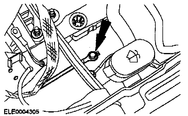
4. Disconnect the ground cable.
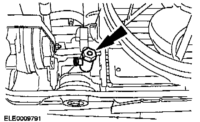
5. WARNING: Danger of scalding if the engine is warm. Failure to do so may result in personal injury.
Drain the coolant (shown from below).
^ Screw the drain plug back in after draining.

6. NOTE: Use an Allen key to prevent the piston rod from turning.
Slacken the suspension strut nuts by five turns on both sides (right-hand side shown).
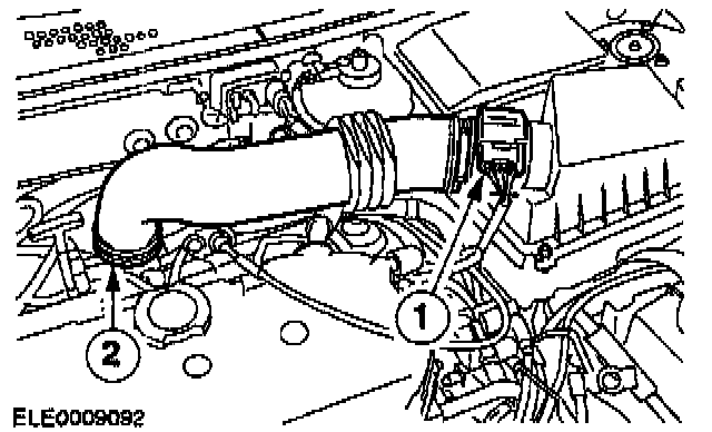
7. Remove the air cleaner (ACL) housing.
1. Pull off the plug of the mass air flow (MAF) sensor.
2. Remove the intake hose.
^ Remove the air cleaner housing from the rubber bushing.

8. Remove the air cleaner intake pipe.
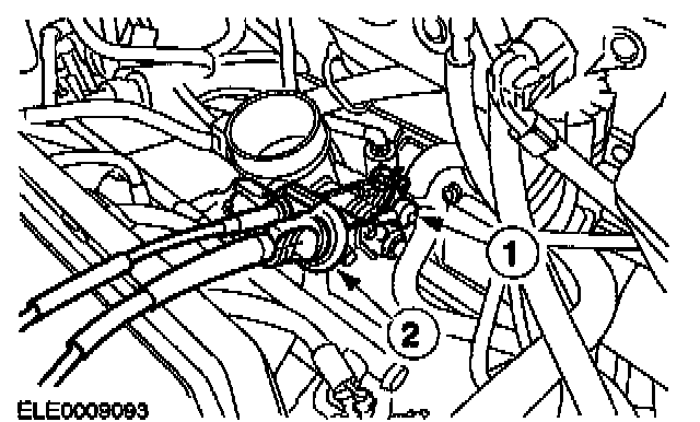
9. Remove the accelerator cable.
1. Unhook the cable.
2. Pull off the plastic clip and lay the accelerator cable to one side.
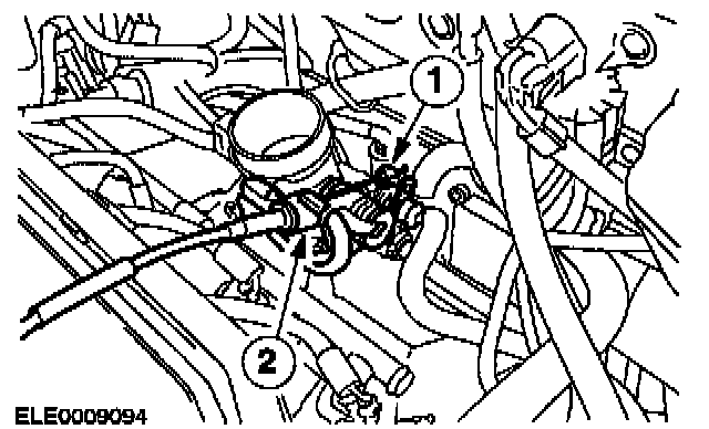
10. Remove the speed control cable.
1. Unhook the cable.
2. Pull off the plastic clip and lay the speed control cable to one side.
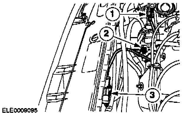
11. Disconnect the electrical connectors
1. Power steering pump pressure switch
2. Generator
3. Heated oxygen sensor (HO2S)
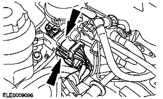
12. Disconnect both powertrain control module (PCM) connectors.
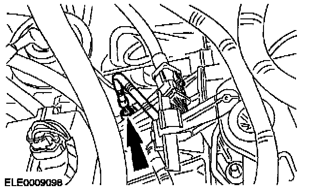
13. Disconnect the vehicle speed sensor (VSS) electrical connector.
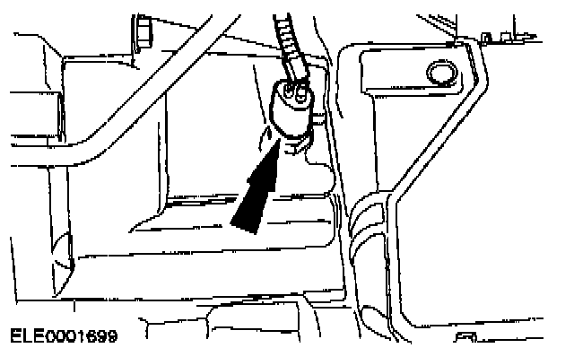
14. Disconnect the reversing lamp switch electrical connector.
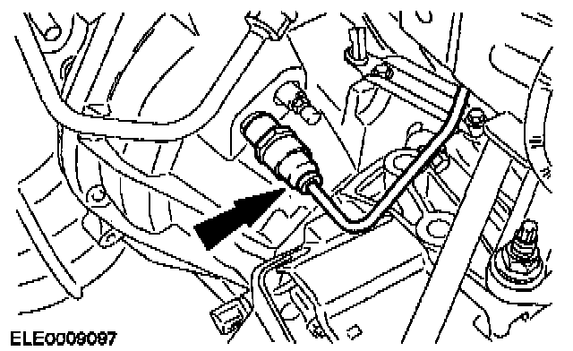
15. CAUTION: Escaping brake fluid. Observe the safety regulations for working with brake fluid.
Remove the high-pressure pipe from the clutch slave cylinder.
^ Pull out the clip.
^ Pull out the high-pressure tube and tie it up with cable ties.
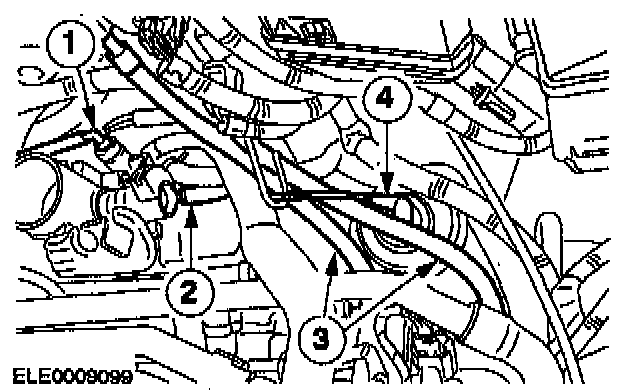
16. Remove the vacuum hoses.
1. EVAP
2. Brake servo
3. Delta Pressure Feedback Electronic (DPFE) system sensor
4. EGR-valve
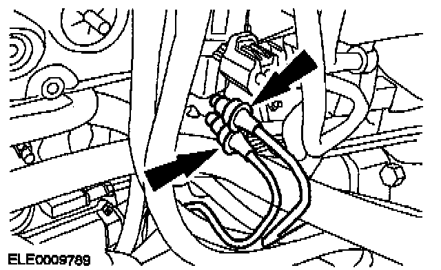
17. Remove the vacuum hose.
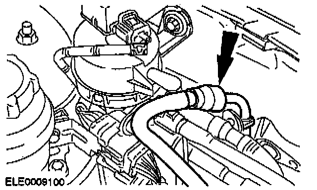
18. WARNING: Escaping fuel. Observe the safety regulations for working with fuel. Failure to do so may result in personal injury.
Drain off the fuel.
^ Remove the fuel hose.
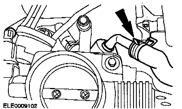
19. Remove the coolant hose from the intake manifold.

20. Remove the coolant hose from the water pump.
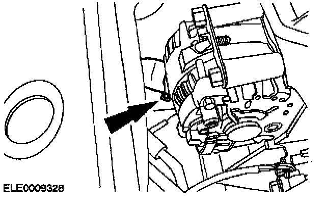
21. Remove the coolant hose from the coolant pipe.
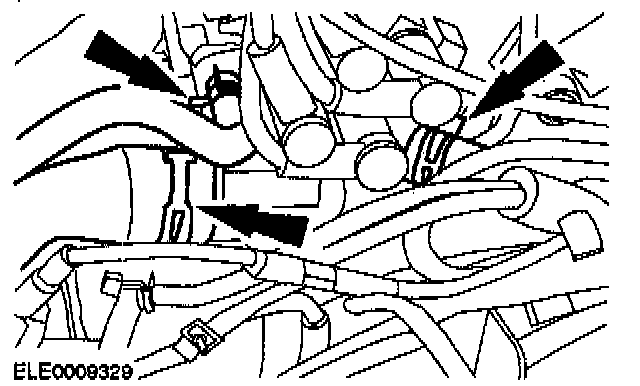
22. Remove the coolant hoses from the coolant hose connectors.
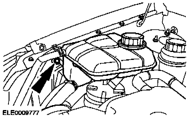
23. Remove the coolant expansion tank and lay it to one side.

24. Slacken the accessory drive belt and remove it.
^ Turn the belt tensioner clockwise.
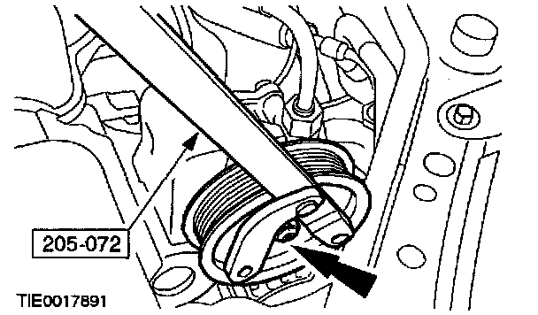
25. NOTE: Using the special tool to prevent the power steering pump pulley from rotating remove the power steering pump pulley retaining nut.
Remove the power steering pump pulley.
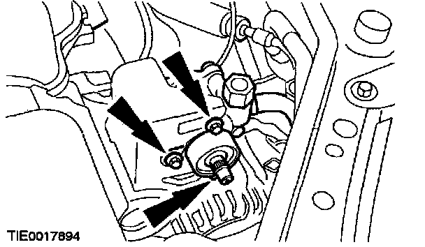
26. Remove the power steering pump and position it to one side.
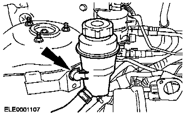
27. Remove the PAS reservoir and position it to one side.
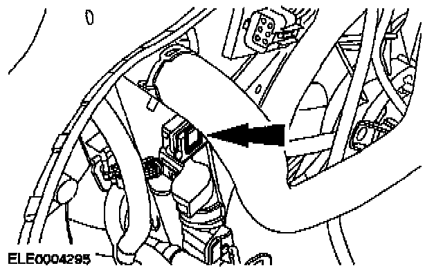
28. Remove the radiator fan.
^ Unclip the clips on both sides (left-hand side shown).
^ Remove the air deflector upwards.
29. Remove the catalytic converter.
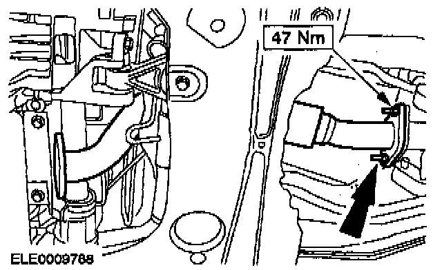
30. Remove the flexible exhaust pipe.
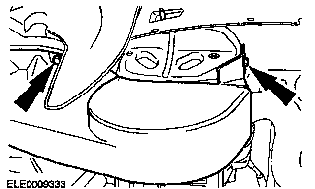
31. Remove the drive belt cover.
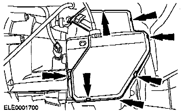
32. Remove the cover of the shift cable and selector cable.
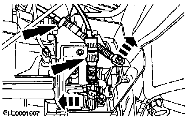
33. Remove the shift cable and selector cable.
^ Remove the shift cable and selector cable by turning the abutment collar clockwise out of the bracket.
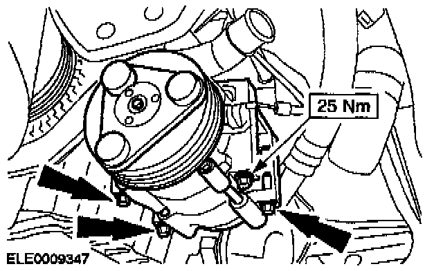
Vehicles with air conditioning
34. Remove the air conditioning compressor and secure it to the radiator crossmember.
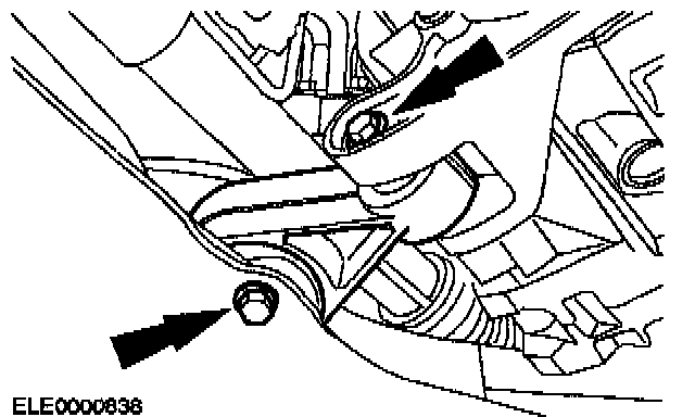
All vehicles
35. Remove the right-hand engine support insulator.
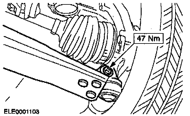
36. Remove both suspension arms (right-hand side shown).
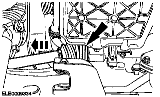
37. CAUTION: The inner joint must not be bent at more than 18 degrees; the outer joint must not be bent at more than 45 degrees.
Remove the right-hand front drive halfshaft from the intermediate shaft.
^ Remove the clamping strap.
^ Pull the front drive halfshaft from the intermediate shaft and tie it up with cable ties.
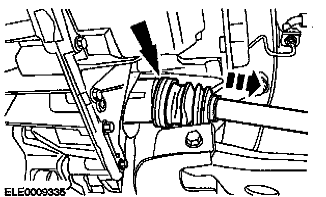
38. CAUTION: The inner joint must not be bent at more than 18 degrees; the eater joint must not be bent at more than 45 degrees.
Remove the left-hand front drive halfshaft from the tripod housing.
^ Remove the clamping strap.
^ Pull the front drive halfshaft from the tripod housing and tie it up with cable ties.
Position the assembly stand with wooden blocks on it under the vehicle.
40. Carefully lower the vehicle until the engine and transaxle assembly is on the assembly stand.
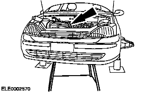
41. Secure the engine and transaxle assembly on the assembly stand with a retaining strap.
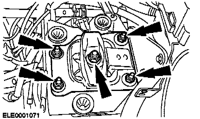
42. Remove the engine rear mount.
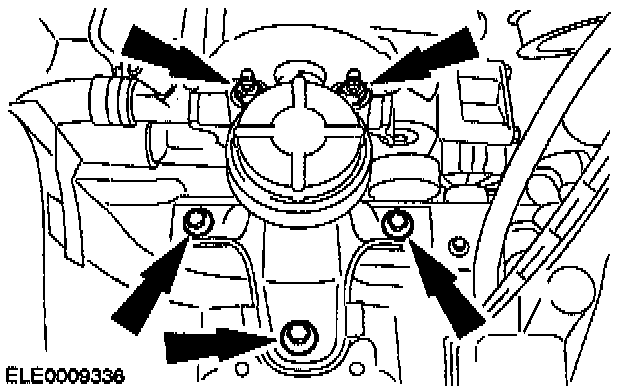
43. Remove the engine front mount.
44. Carefully raise the vehicle.
^ Secure the engine and transaxle assembly with a retaining strap on the assembly table.
^ Pull the assembly stand forward with the engine and transaxle assembly.
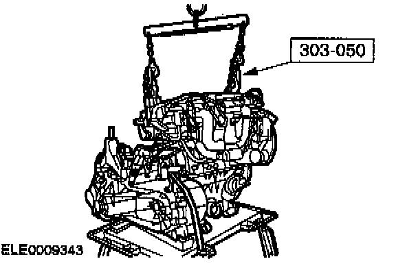
45. Use a floor crane and the special tool to separate the engine from the transaxle.
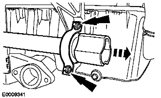
46. Remove the retaining clip.
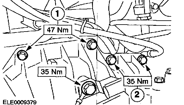
47. Remove the transaxle upper bolts.
1. Flange bolts
2. Starter motor bolts
^ Disconnect the ground cable.
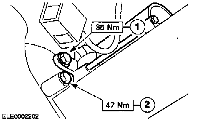
48. Remove the right-hand transaxle flange bolt and remove the starter motor.
1. Starter motor bolt
2. Flange bolt
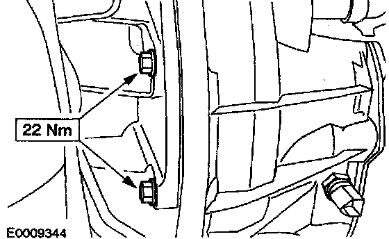
49. Remove the transaxle left-hand flange bolts.
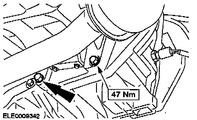
50. Remove the transaxle lower flange bolts.
51. Separate the engine from the transaxle.