Main Control Valve Body
Main Control Valve BodySpecial Tools:
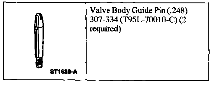
Special Tool(s)
Removal
l. NOTE: When the battery is disconnected or a new battery installed, certain transmission operating parameters can be lost. The powertrain control module (PCM) must relearn these parameters. During this learning process, you may experience slightly firm shifts, delayed, or early shifts. This operation is considered normal and will not affect the function of the transmission. Normal operation will return once these parameters are stored by the PCM.
Disconnect the battery ground cable.
2. Raise and support the vehicle.
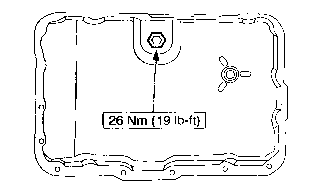
3. Drain the transmission fluid.
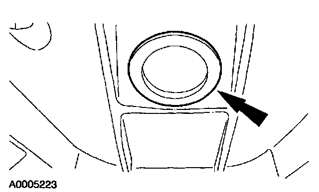
4. Remove the converter housing plug.
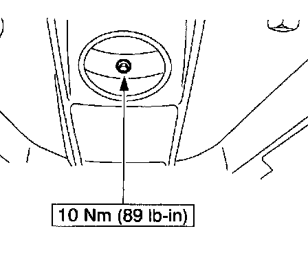
5. Remove the drain plug.
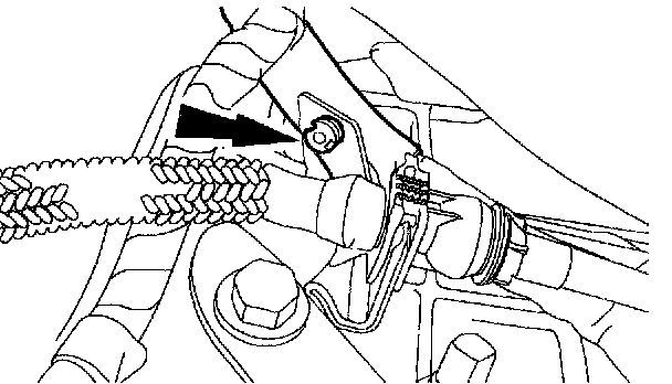
6. Disconnect the wire harness from the top of the transmission shift cable bracket.
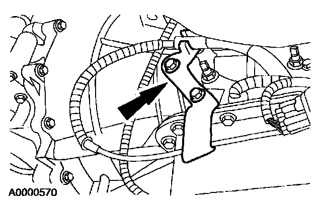
7. Remove the transmission shift cable bracket and position out of the way.
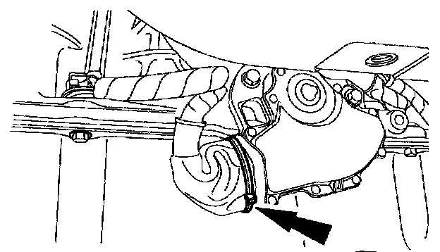
8. Remove and discard the tie strap from the digital TR sensor connector.
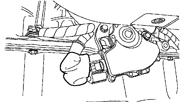
9. Slide the rubber boot back to gain access to the connector and disconnect the digital transmission range (TR) sensor connector.
10. NOTE: Clean the area around connector to prevent contamination of the solenoid body connector.
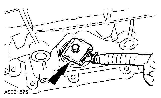
Disconnect the transmission connector.
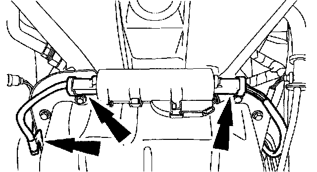
11. Disconnect the H02S sensor connectors and remove the sensor wire retaining clip from the right side of the transmission pan rail.
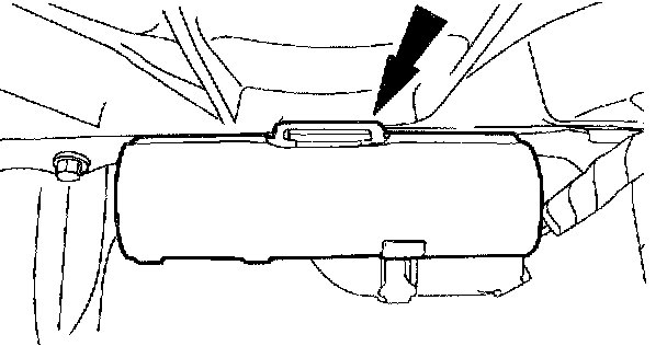
12. Remove the H02S sensor connector from the front of the transmission pan rail.
13. NOTE: The transmission fluid pan gasket is reusable. Clean and inspect for damage. If not damaged, the gasket should be reused.
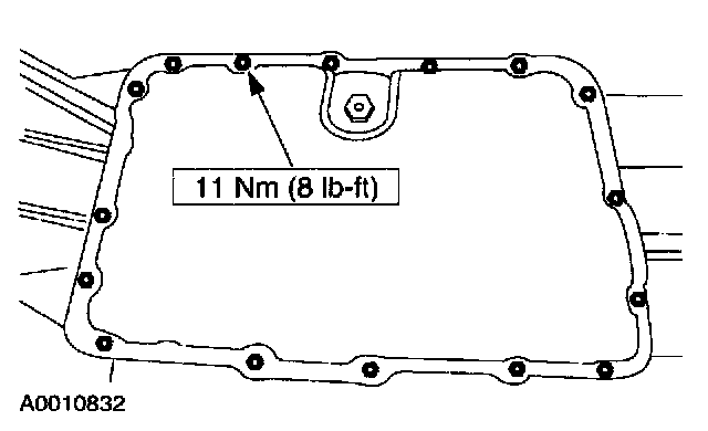
Remove the transmission fluid pan and gasket.
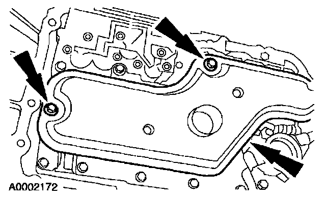
14. Remove the transmission fluid filter.
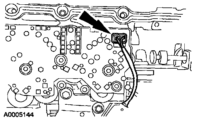
15. Disconnect the reverse pressure switch connector.
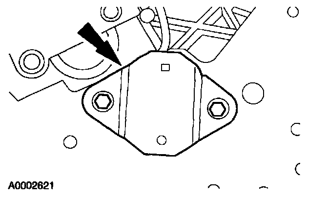
16. Remove the reverse pressure switch and discard.
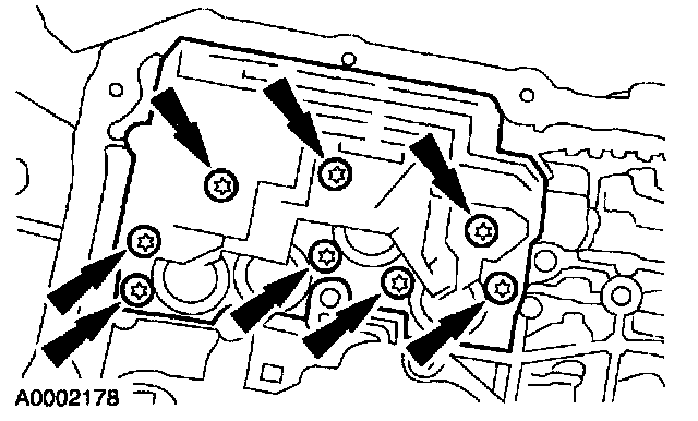
17. Remove the solenoid body.
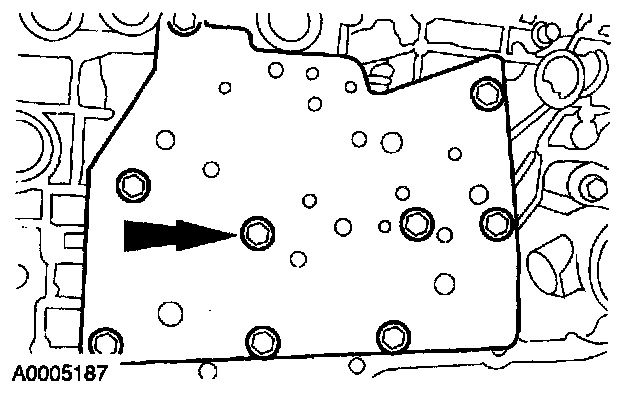
18. Remove the valve body cover plate and gasket.
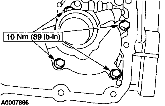
19. Remove the reverse servo.
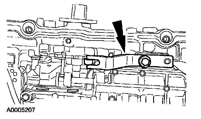
20. Remove the manual control valve detent spring.
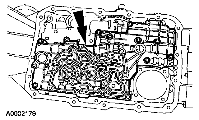
21. Remove the main control valve body, separator plate and gasket.
22. NOTE: The intermediate clutch spring and seal will fall out of the case.
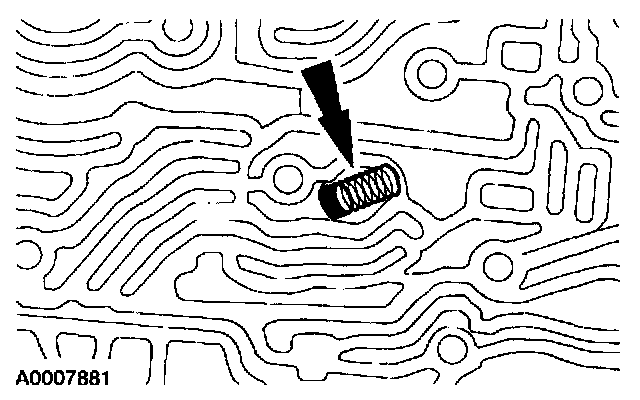
Remove the intermediate clutch spring and seal.
Installation
1. CAUTION: The intermediate clutch fluid inlet tube seal and spring must be correctly seated in the case. Failure to correctly seat the inlet tube seal and spring will cause an internal fluid leak and transmission damage.
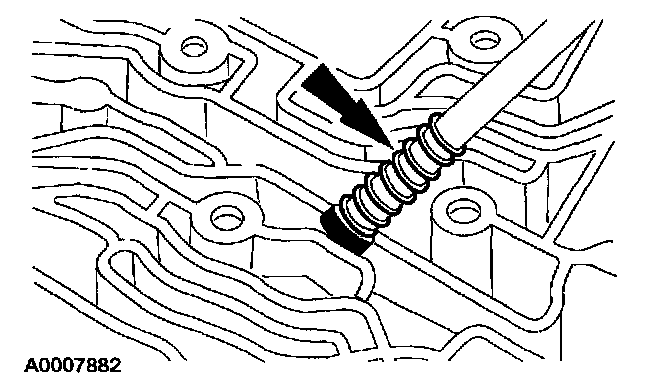
Using a drift punch, correctly install and seat the intermediate clutch fluid inlet tube seal and spring into the case.
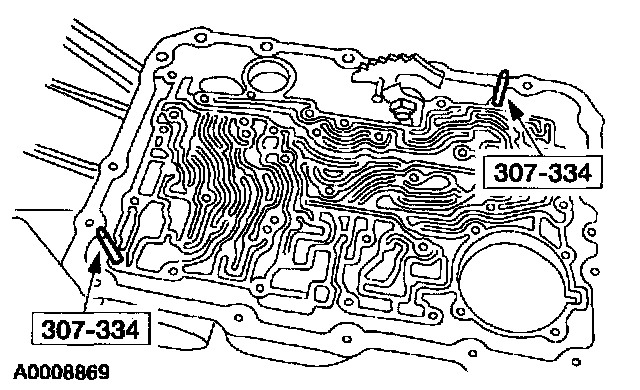
2. Install the special tools into the transmission case.
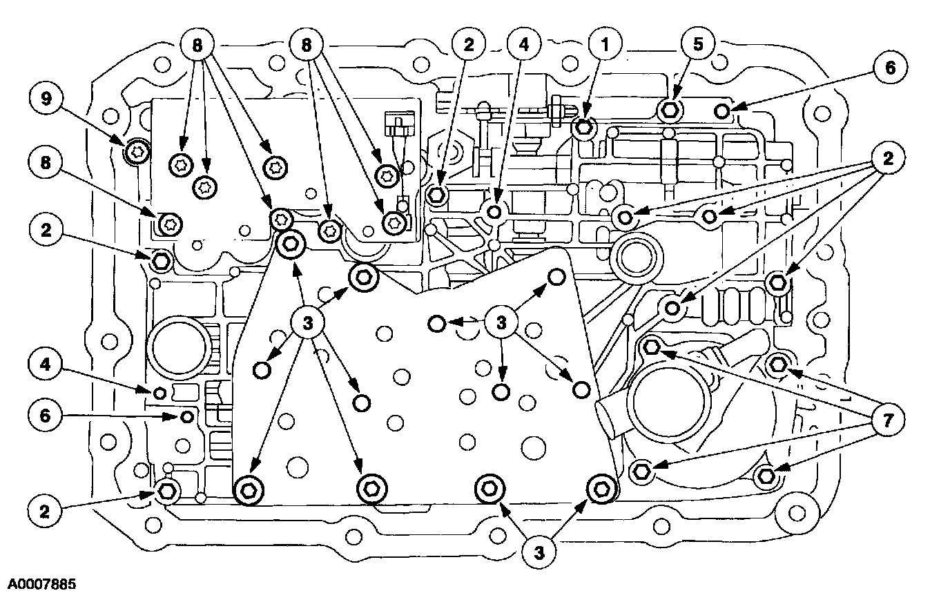
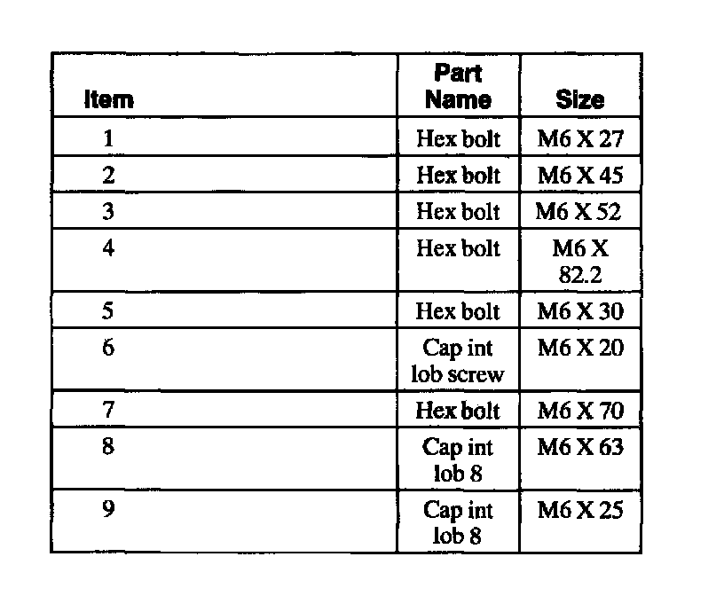
3. Refer to the chart for bolt locations.
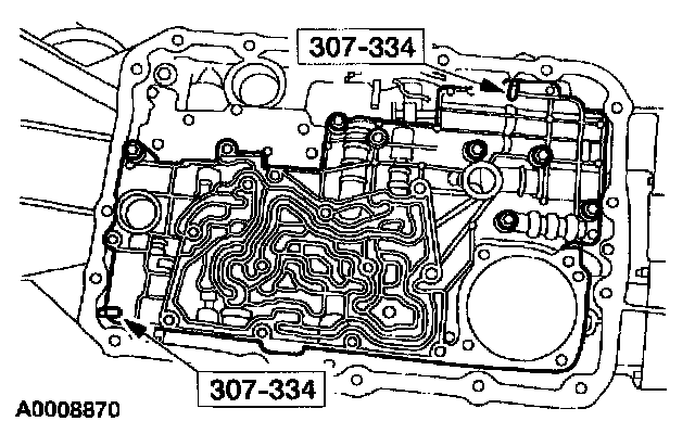
4. Install the main control valve body and loosely install the screws.
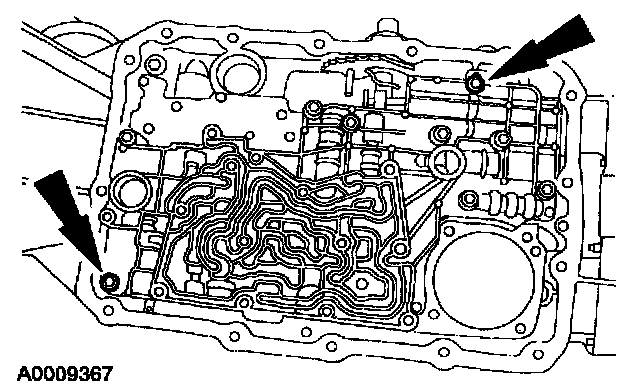
5. Remove the special tools and loosely install the screws.
6. Install the valve body cover plate and gasket and loosely install the screws.
7. Install the reverse pressure switch and loosely install the screws.
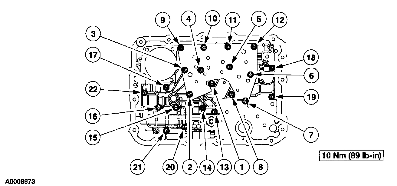
8. Tighten the screws in the sequence shown.
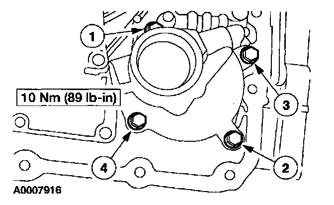
9. Install the reverse servo. Tighten the bolts in sequence shown in two stages.
^ Stage 1: Tighten bolts to 5 Nm (44 inch lbs.)
^ Stage 2: Tighten bolts to 11 Nm (8 ft. lbs.)
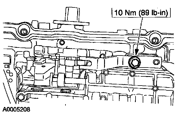
10. Install the manual control valve detent spring.
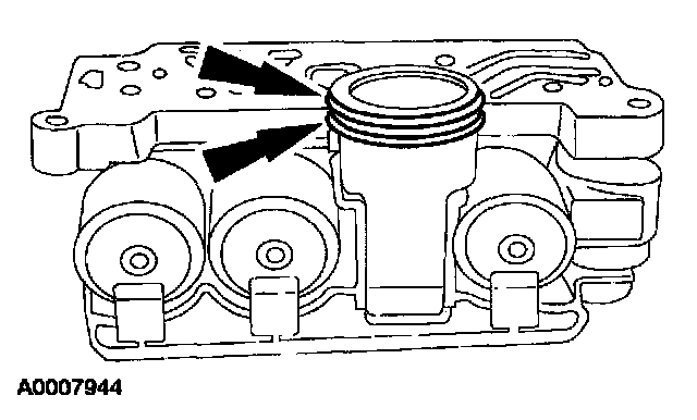
11. Install new O-ring seals on the solenoid body connector. Lubricate the O-ring seals with clean automatic transmission fluid.
12. CAUTION: Inspect the transmission case bore to make sure it is free of foreign material and not damaged. If it is damaged, transmission leak may occur.
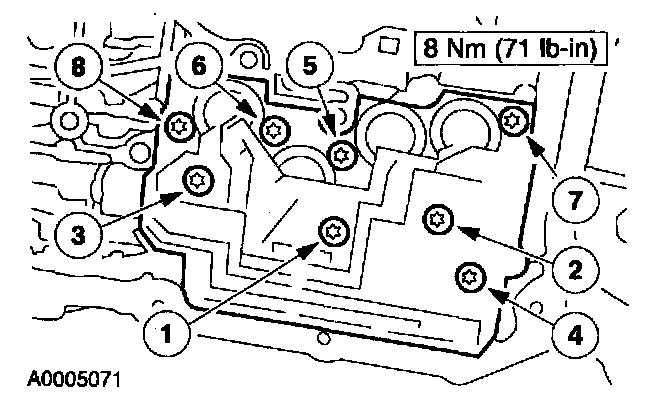
Install the solenoid body. Tighten the bolts in sequence shown.
13. Connect the reverse pressure switch connector.
14. CAUTION: Lubricate the fluid filter O-ring seals with clean automatic transmission fluid or seals can be damaged.
NOTE: Make sure that the fluid filter O-ring seals are correctly seated on the filter.
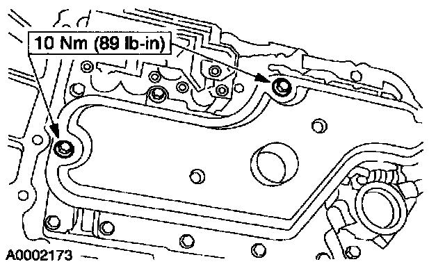
Lubricate the seals and install the transmission fluid filter.
15. NOTE: The transmission fluid pan gasket is reusable. Clean and inspect for damage. If not damaged, the gasket should be reused.
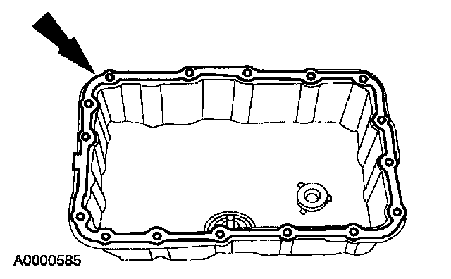
Install the transmission fluid pan and gasket and loosely install the screws.
16. Tighten the screws in a crisscross sequence.
17. Install the H02S sensor connector to the front of the transmission pan rail.
18. Reconnect the H02S sensor connectors and install the sensor wire retaining clip to the right side of the transmission pan rail.
19. NOTE: A new converter drain plug must be used to prevent leakage.
Install the drain plug.
20. Install the converter housing access plug.
21. CAUTION: Damage to the solenoid body assembly can result if the screw is tightened above specification.
NOTE: Always install new O-ring seals on vehicle harness connector.
NOTE: Clean the area around connector to prevent contamination of the solenoid body connector.
NOTE: Use petroleum jelly to lubricate the O-ring seals to aid in the installation process.
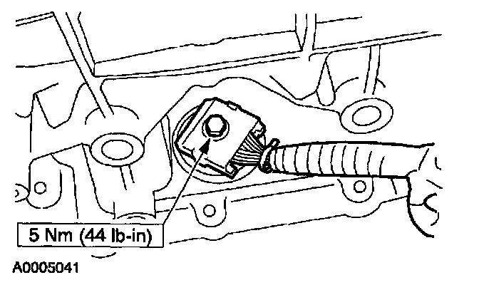
Install and lubricate new O-ring seals on the transmission connector and connect the connector.
22. Reconnect the digital TR sensor connector and slide the rubber boot over the connector.
23. Install a new tie strap around the rubber boot for the TR sensor connector.
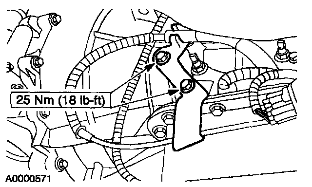
24. Install the transmission shift cable bracket.
25. Reconnect the wire harness to the top of the transmission shift cable bracket.
26. Lower the vehicle.
27. NOTE: When the battery is disconnected or a new battery installed, certain transmission operating parameters can be lost. The powertrain control module (PCM) must relearn these parameters. During this learning process, you may experience slightly firm shifts, delayed, or early shifts. This operation is considered normal and will not affect the function of the transmission. Normal operation will return once these parameters are stored by the PCM.
Connect the battery ground cable.
28. Fill the transmission to the correct fluid level and check for correct transmission operation.