Timing Cover: Service and Repair
Engine Front CoverRemoval
All vehicles
1. Remove the air intake scoop bracket.
2. Remove the RH valve cover.
3. Remove the Hydro-Boost brake booster.
Manual transmission vehicles
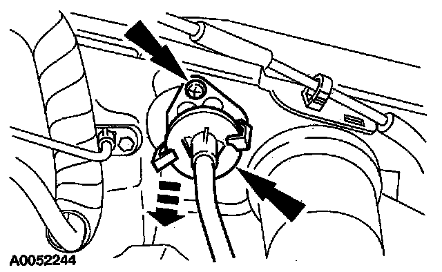
4. Remove the two clutch release cable retaining screws.
All vehicles
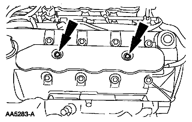
5. Remove the LH ignition coil cover bolts and the cover.
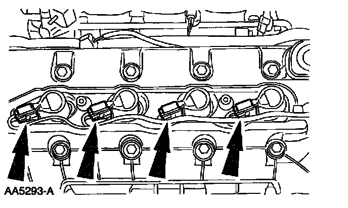
6. Disconnect the ignition coil electrical connectors.
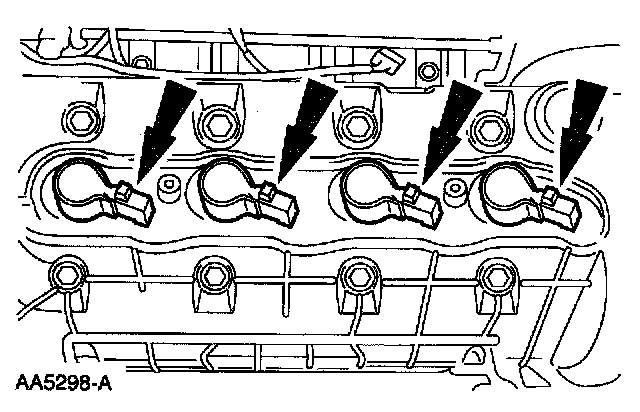
7. Remove the ignition coils.
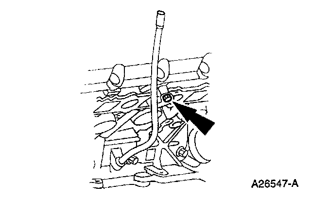
8. Remove the bolt and position the oil level indicator tube aside.
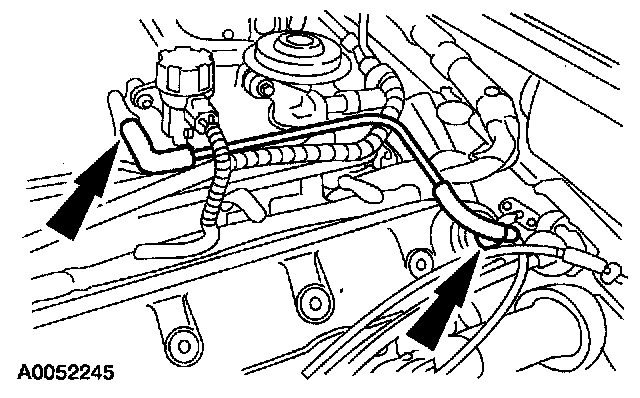
9. Remove the Positive Crankcase Ventilation (PCV) valve hose and disconnect the electrical connector.
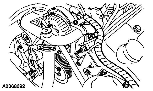
10. Disconnect the wiring harness anchor from the valve cover.
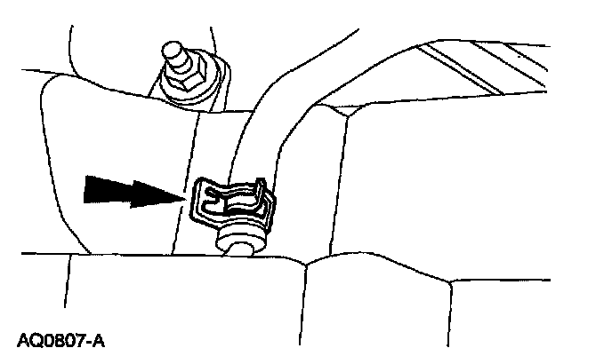
11. Remove the degas bottle vent hose.
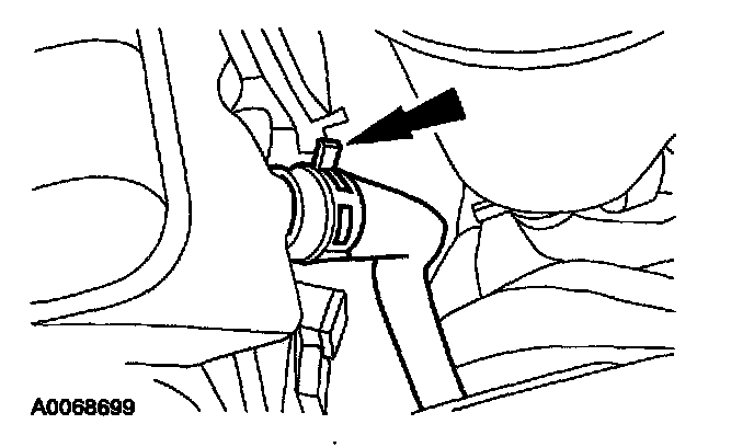
12. Remove the degas bottle return hose.
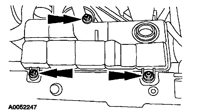
13. Remove the nuts and the degas bottle.
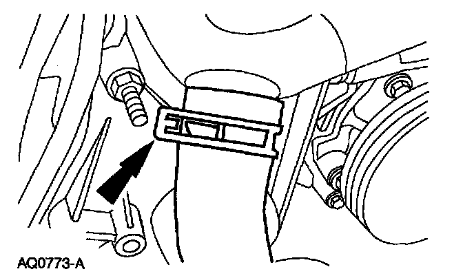
14. Disconnect the upper radiator hose from the bypass tube.
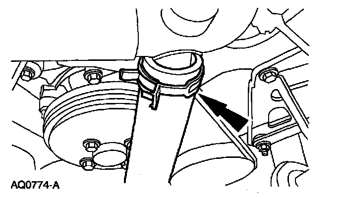
15. Disconnect the lower radiator hose from the bypass tube.
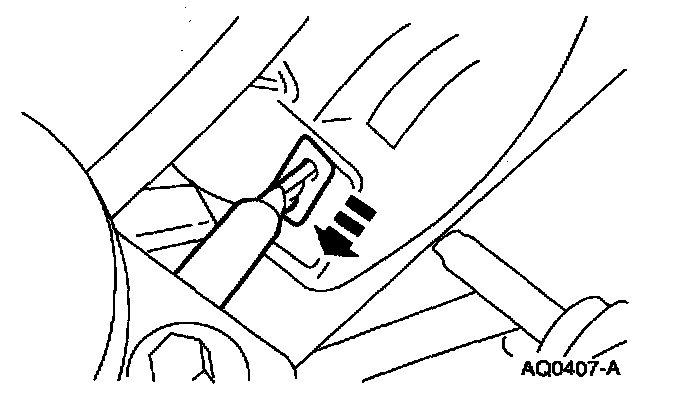
16. Disconnect the cooling fan electrical connector.
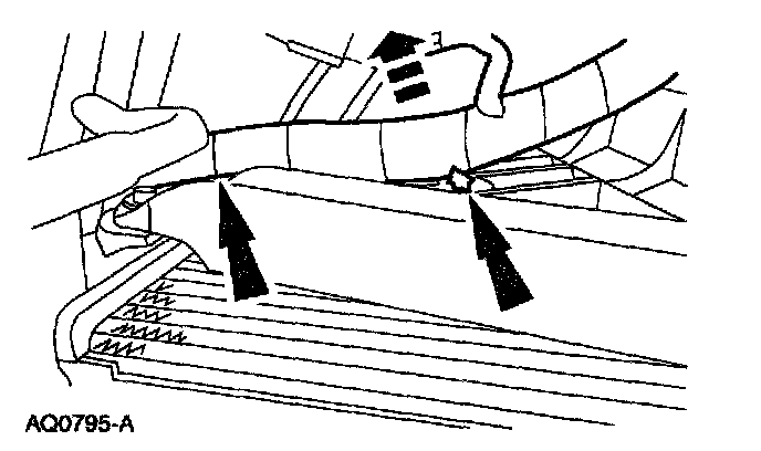
17. Separate the cooling fan wiring harness from the fan shroud.
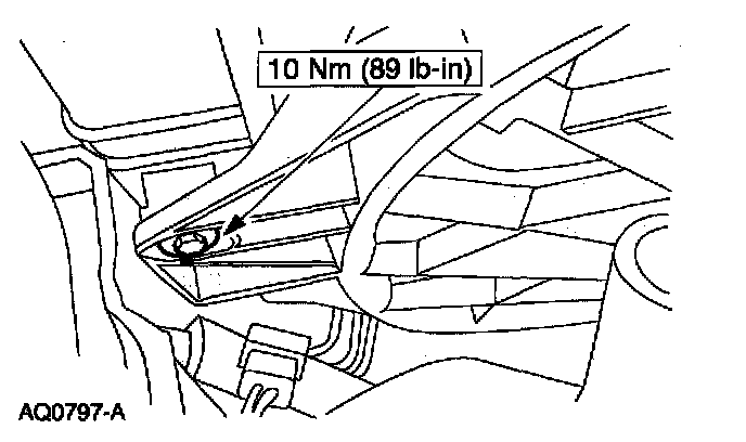
18. Remove the LH cooling fan shroud bolt.
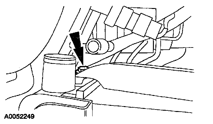
19. Remove the RH cooling fan shroud bolt.
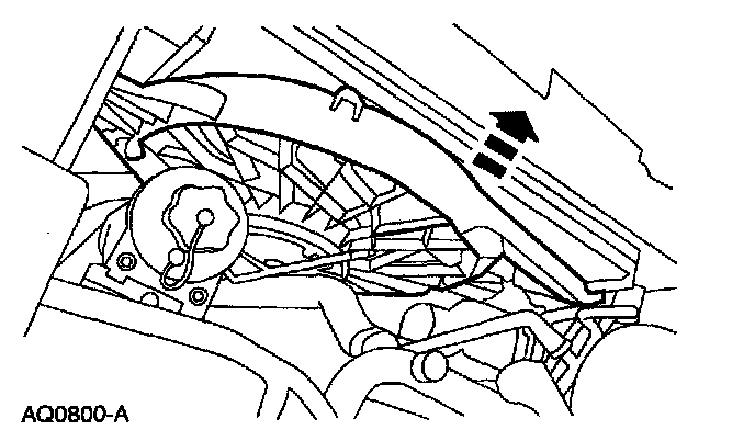
20. Remove the cooling fan and shroud as an assembly.
21. Remove the crankshaft front oil seal.
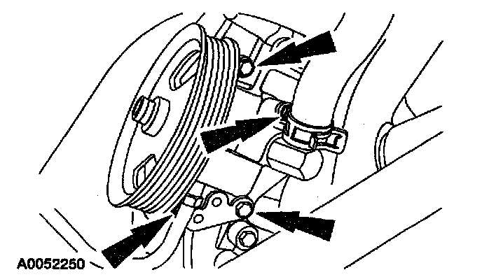
22. Remove the three bolts shown. Loosen the fourth bolt (hidden behind the p/s tube). Position the power steering pump aside.
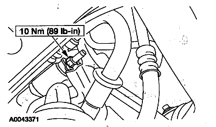
23. Remove the A/C muffler bracket nut.
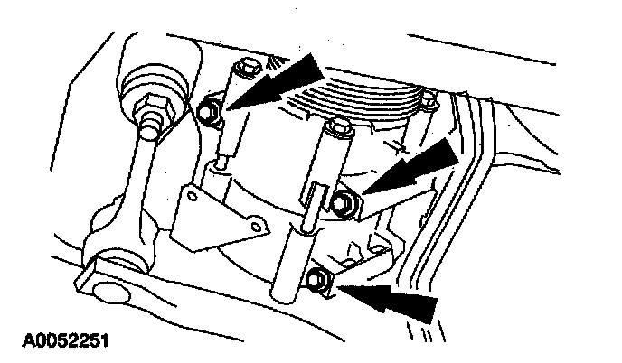
24. Remove the bolts and position the A/C compressor aside.
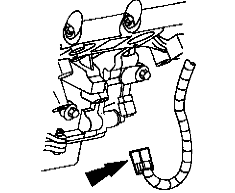
25. Disconnect the Crankshaft Position (CKP) sensor electrical connector.
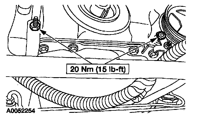
26. Remove the wiring harness nuts and position the wiring harness aside.
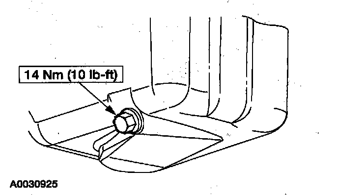
27. Remove the drain plug and drain the oil.
^ Install the drain plug when finished.
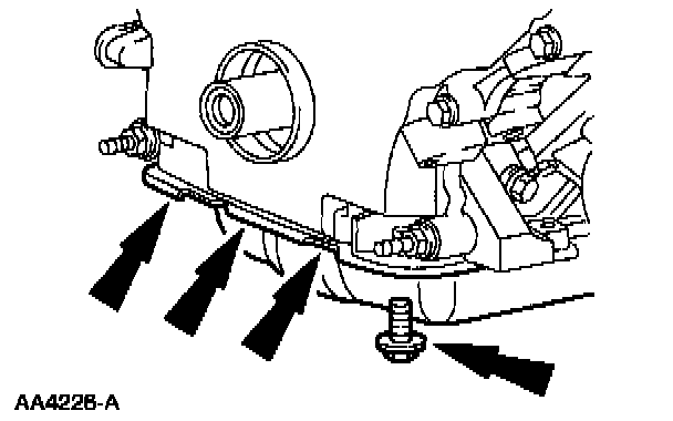
28. Remove the front four oil pan bolts.
Manual transmission vehicles
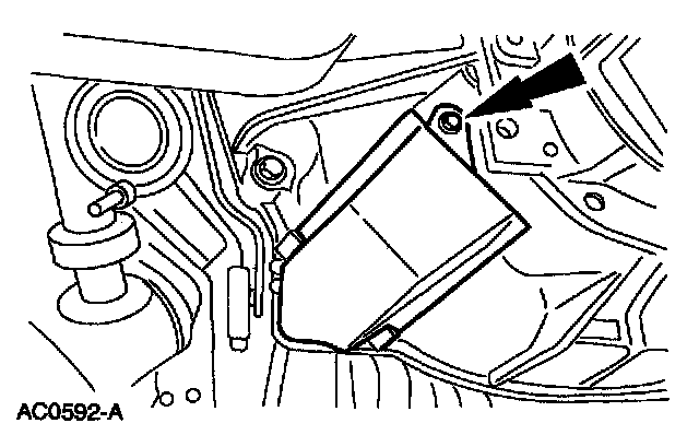
29. Remove the bolt and the clutch release cable shield.
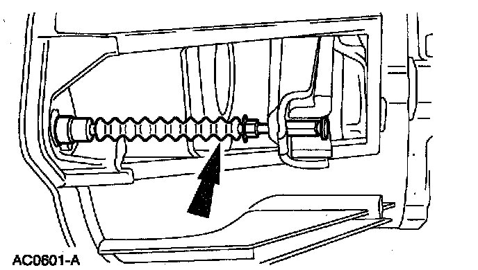
30. Disengage the clutch release cable from the clutch release fork.
31. Lower the vehicle.
All vehicles
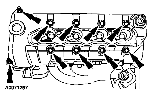
32. Remove the LH valve cover.
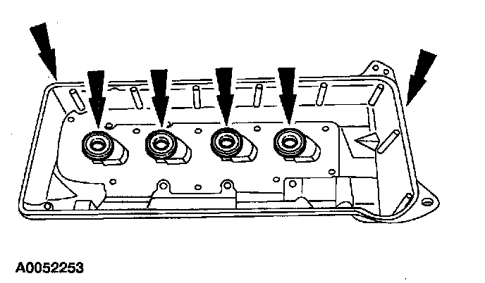
33. CAUTION: Do not use metal scraper, wire brushes, power abrasive discs or other abrasive means to clean the sealing surfaces. These tools cause scratches and gouges which make leak paths. Use a plastic scraping tool to remove all traces of old sealant.
Clean and inspect sealing surfaces and valve cover gaskets. If necessary, install new gaskets. Make sure the gaskets are correctly seated on the valve cover.
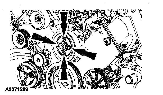
34. Remove the four bolts and the coolant pump pulley.
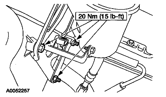
35. Remove the three bolts and position the power steering reservoir and bracket assembly aside.
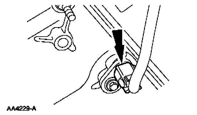
36. Disconnect the Camshaft Position (CMP) sensor electrical connector.
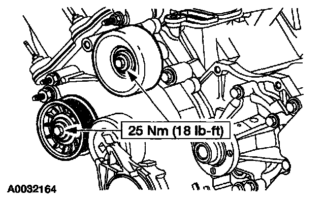
37. Remove the idler pulleys.
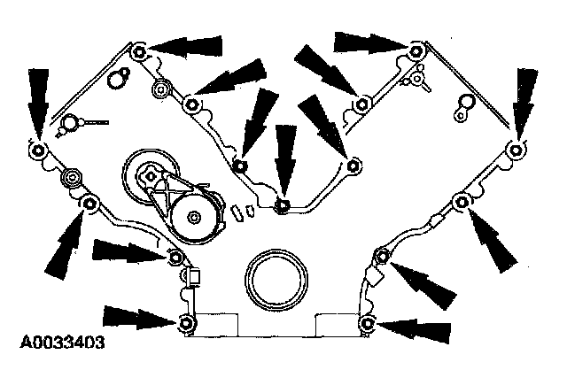
38. Remove the bolts and the studs and remove the engine front cover.
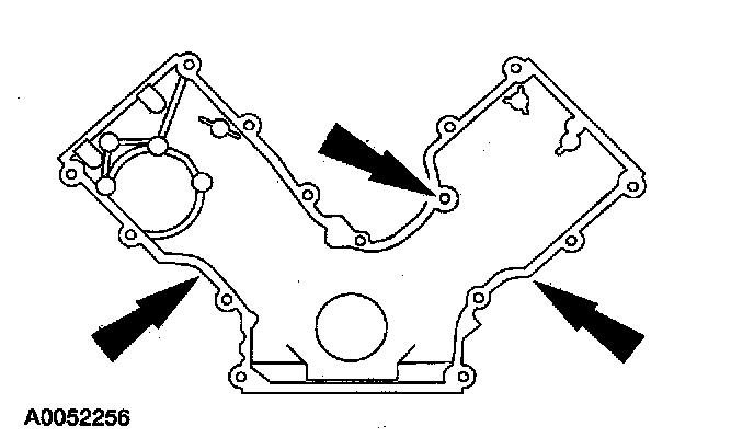
39. CAUTION: Do not use metal scrapers, wire brushes, power abrasive discs or other abrasive means to clean the sealing surfaces. These tools cause scratches and gouges which make leak paths. Use a plastic scraping tool to remove all traces of old sealant.
Remove and discard the gasket. Clean and inspect the sealing surfaces.
Installation
All vehicles
1. Position the engine front cover gasket on the engine front cover..
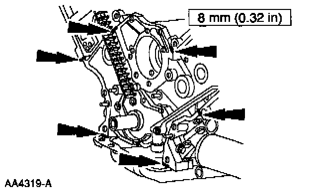
2. NOTE: If the engine front cover is not secured within four minutes, the sealant must be removed and the sealing area cleaned with metal surface cleaner. Allow to dry until there is no sign of wetness, or four minutes, whichever is longer. Failure to follow this procedure can cause future oil leakage.
Apply the silicone gasket and sealant along the cylinder head-to-cylinder block surface and the oil pan-to-cylinder block surface.
Part 2 Of 2:
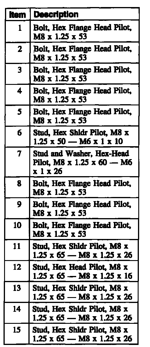
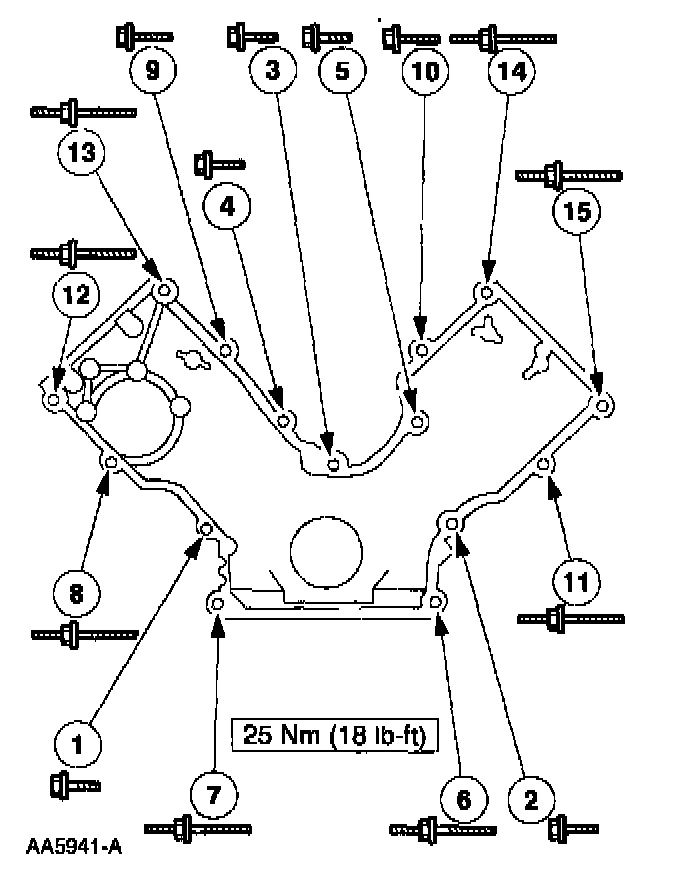
3. Install the engine front cover and tighten the bolts and studs in sequence shown.
4. Install the idler pulleys.
5. Connect the Camshaft Position (CMP) sensor electrical connector.
6. Position the power steering reservoir and bracket assembly and install the bolts.
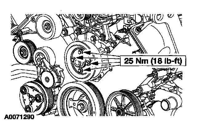
7. Install the coolant pump pulley and the bolts.
8. Install the LH valve cover and loosely install the bolts.
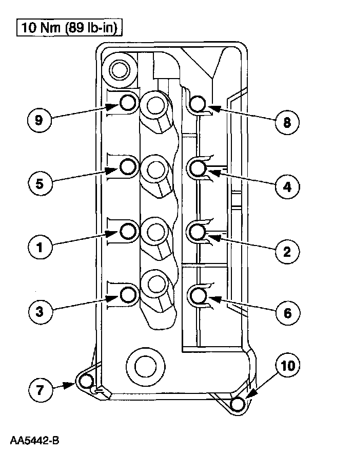
9. Tighten the LH valve cover bolts in the sequence shown.
10. Raise and support the vehicle.
Manual transmission vehicles
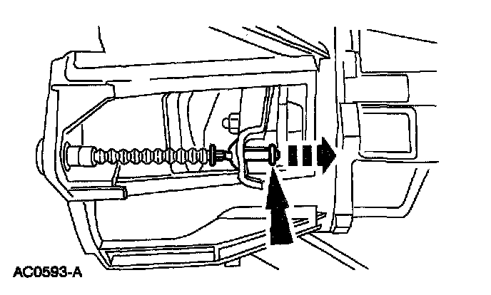
11. Connect the clutch release cable to the clutch release fork.
12. Install the clutch release cable shield and the bolt,
All vehicles
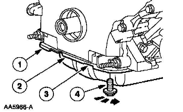
13. Loosely install the four oil pan bolts. Tighten the bolts in three stages, and in the sequence shown.
1 Stage 1: Tighten the bolts to 2 Nm (18 inch lbs.).
2 Stage 2: Tighten the bolts to 20 Nm (15 ft. lbs.).
3 Stage 3: Tighten the bolts an additional 90° (1/4 turn).
14. Position the wiring harness and install the nuts.
15. Connect the Crankshaft Position (CKP) sensor electrical connector.
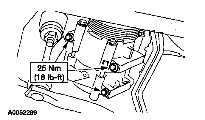
16. Position the A/C compressor, A/C muffler, and the hose. Install the bolts.
17. Install the A/C muffler bracket nut.
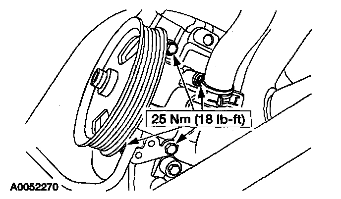
18. Position the power steering pump and install the bolts.
19. Install the crankshaft front oil seal.
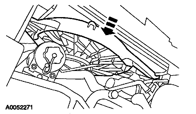
20. Position the cooling fan and shroud in the installed position.
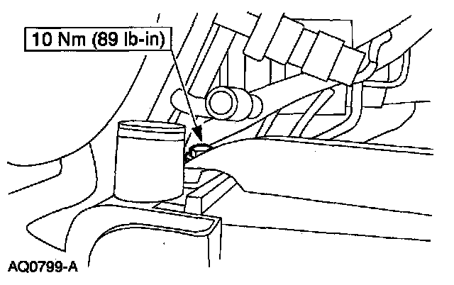
21. Install the RH cooling fan bolt.
22. Install the LH cooling fan bolt.
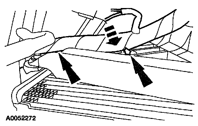
23. Attach the cooling fan wiring harness to the fan shroud.
24. Connect the cooling fan electrical connector.
25. Connect the lower radiator hose to the bypass tube.
26. Connect the upper radiator hose to the bypass tube.
27. Install the degas bottle and the nuts.
28. Connect the degas bottle return hose.
29. Connect the degas bottle vent hose.
30. Connect the wiring harness anchor to the valve cover.
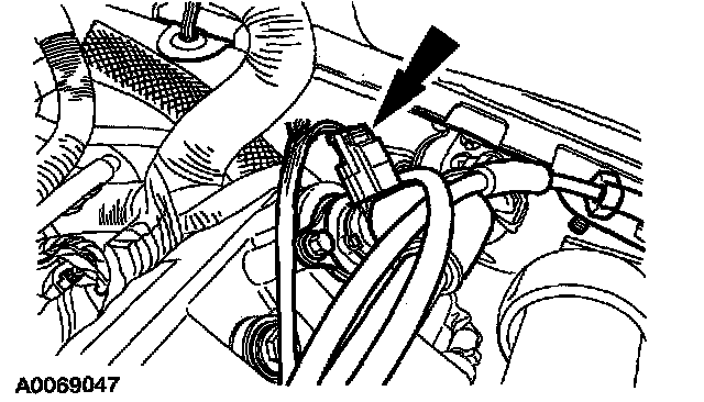
31. Install the Positive Crankcase Ventilation (PCV) valve hose and connect the electrical connector.
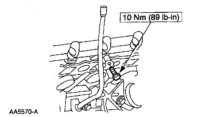
32. Position the oil level indicator tube and install the bolt.
33. Install the LH ignition coils.
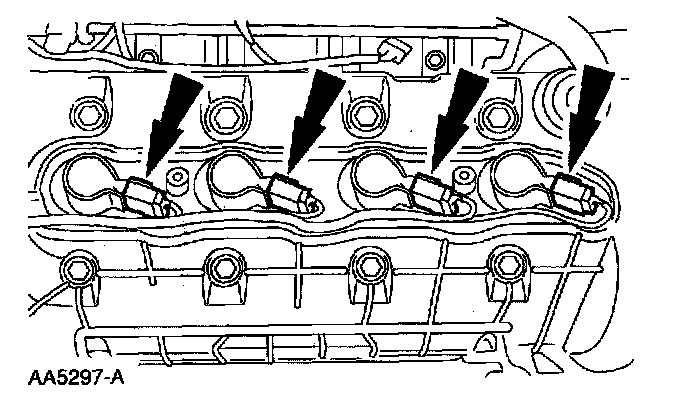
34. Connect the LH ignition coil electrical connectors.
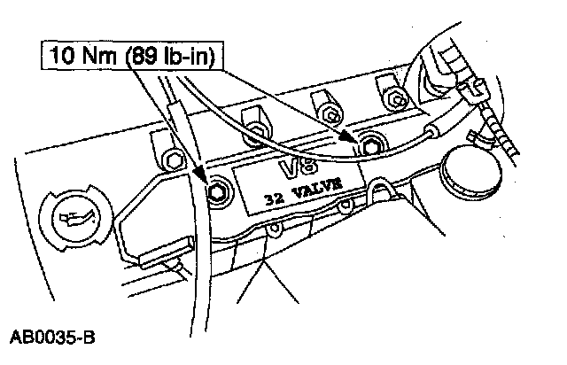
35. Install the LH coil cover and install the bolts.
Manual transmission vehicles
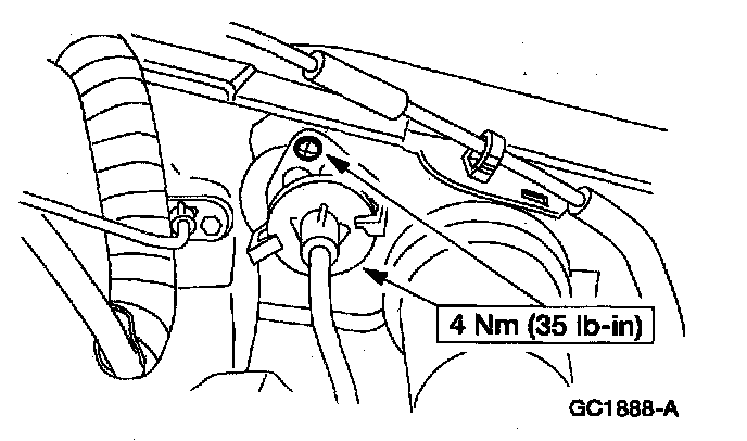
36. Install the clutch release cable screws.
All vehicles
37. Install the RH valve cover.
38. Install the Hydro-Boost brake booster.
39. Install the air intake scoop bracket.
40. Fill the crankcase with clean engine oil.