Disassembly/Assembly
Fig. 1 Unstaking Lock Washer:
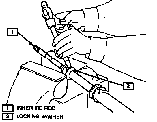
Fig. 2 Removing Inner Tie Rod Assembly:
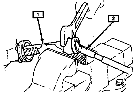
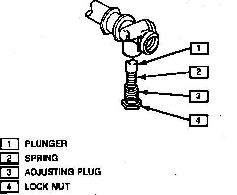
Fig. 3 Adjusting Plug, Spring And Plunger Assembly:
DISASSEMBLY
1. Remove retaining ring and dust boot from rack.
2. Clamp steering gear in suitable vise.
3. Remove clamps from tie rod boots, then separate boots from rack and slide down tie rods.
4. Unstake locking washers between inner tie rods and rack, Fig. 1.
5. Remove right tie rod, then left tie rod assembly from rack, Fig. 2.
6. Loosen adjusting plug nut, then remove spring and rack plunger, Fig. 3.
Fig. 4 Pinion Shaft Measurement Location:
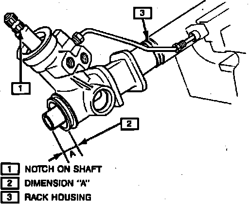
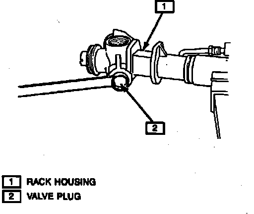
Fig. 5 Removing Valve Plug:
7. Center rack and mark position of pinion valve. Rotate pinion gear until notch is parallel to rack, then carefully measure and record dimension ``A'', Fig. 4. This measurement must be used upon reassembly.
8. Remove valve plug, Fig. 5.
Fig. 6 Removing Pinion Fixing Nut:
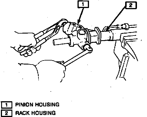
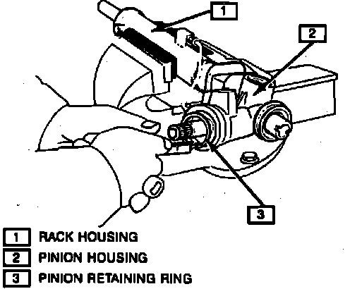
Fig. 7 Removing Retaining Snap Ring:
9. Remove pinion fixing nut, Fig. 6.
10. Remove pinion retaining snap ring, Fig. 7.
11. Remove rack from housing.
Fig. 8 Removing Inner Rack Seal & Shock Damper:
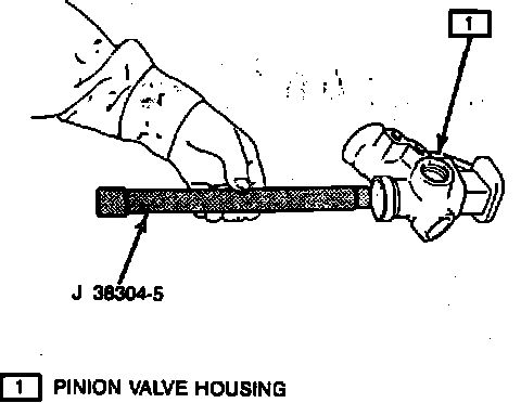
Fig. 9 Removing Pinion Bearing:
12. Remove inner rack seal and shock damper using inner rack seal remover tool No. 38304-5, Fig. 8.
13. Remove lower pinion bearing from rack housing.
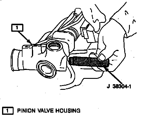
14. Remove bearing and seal from valve housing using lower pinion valve housing seal and bearing remover tool No. 38304-1, Fig. 9.
Fig. 10 Installing Pinion Valve Bearing & Seal:
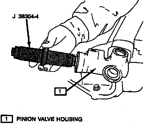
Fig. 11 Installing Inner Rack Seal:
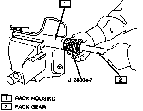
Fig. 12 Seating Inner Rack Seal:
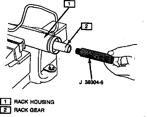
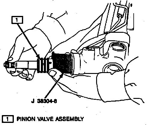
Fig. 13 Installing Pinion Valve Assembly:
ASSEMBLY
1. Install inner rack seal onto rack seal ring installer, tool No. J 33997-3 using rack seal ring expander, tool No. J 33997-2.
2. Install upper bearing and seal into pinion valve housing using lower pinion valve housing seal and bearing installer tool No. J 38304-4, Fig. 10.
3. Install rack into housing and seat inner rack seal using pack piston ring installer tool No. J 38304-7 and inner rack seal installer tool No. J 38304-6, Figs. 11 and 12.
4. Install seal holder on to housing, then retaining ring on seal holder.
5. Install pinion valve assembly into housing using pinion ring compressor tool No. 38304-8, Fig. 13.
6. Install lower bearing on pinion valve.
7. Install pinion fixing nut and torque to 29 ft. lbs.
8. Install pinion valve housing cap, then rack plunger and plunger plug. Torque rack plunger adjusting plug to 44 inch lbs. Back off plug, then torque to 44 inch lbs. Back off plug 26° then, tighten locknut.
9. Install upper pinion valve seal, then retaining ring on upper pinion valve seal.
10. Install left tie rod assembly, then torque inner tie rod to 65 ft. lbs. and peen over stake washer. Install left tie rod boot.
11. Install right tie rod assembly, then torque inner tie rod to 65 ft. lbs. and peen over stake washer. Install right tie rod boot.