ABS Indicator Circuit Troubleshooting
ABS Indicator Circuit Troubleshooting1. Turn the ignition switch ON (II), and watch the TCS indicator.
Does the TCS indicator come on?
YES - If the TCS indicator comes on and goes off, it's OK. If the TCS indicator stays on, go to step 13.
NO - Go to step 2.
2. Turn the ignition switch OFF then ON (II) again.
Does the brake system indicator come on?
YES - Go to step 3.
NO - Repair open in the brake system indicator circuit.
- Blown BACK-UP LIGHT (7.5 A) fuse.
- Open in the wire between the BACK-UP LIGHT (7.5A) fuse and gauge assembly.
- Open circuit inside the fuse box.
3. Turn the ignition switch OFF.
4. Disconnect ABS/TCS control unit connector A (26P).
5. Turn the ignition switch ON (II).
Does the ABS indicator come on?
YES - Check for loose ABS/TCS control unit connectors. If necessary, substitute a known-good ABS/TCS control unit, and recheck.
NO - Go to step 6.
6. Check the ABS indicator bulb in the gauge assembly.
Is the bulb OK?
YES - Go to step 7.
NO - Replace the ABS indicator bulb.
7. Turn the ignition switch OFF.
8. Disconnect gauge assembly connector C (16P).
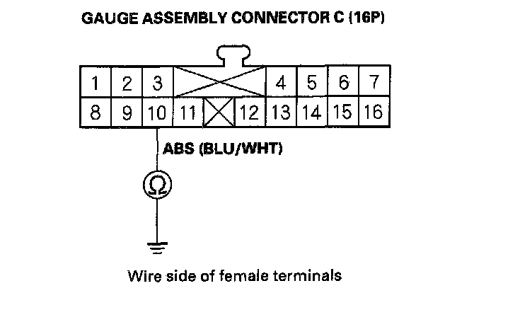
9. Check for continuity between gauge assembly connector G (16P) terminal No. 10 and body ground.
Is there continuity?
YES - Repair short to body ground in the wire between the gauge assembly and the ABS/TCS control unit.
NO - Go to step 10.
10. Connect gauge assembly connector C (16P).
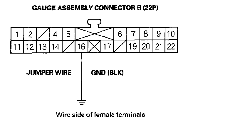
11. Connect gauge assembly connector B (22P) terminal No. 16 to body ground with a jumper wire.
12. Turn the ignition switch ON (II).
Does the ABS indicator come on?
YES - Repair open in the wire between the gauge assembly and body ground (G501).
NO - Replace the printed circuit board in the gauge assembly.
13. Check the R/C MIRROR (7.5 A) fuse in the driver's under-dash fuse/relay box, and reinstall the fuse if it is OK.
Is the fuse OK?
YES - Go to step 14.
NO - Replace the fuse, and recheck.
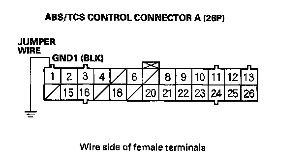
14. Connect ABS/TCS control unit connector A(26P) terminal No. 1 to body ground with a jumper wire.
15. Turn the ignition switch ON (II).
Does the ABS indicator go off?
YES - Repair open in the wire between the ABS/TCS control unit and body ground (G303).
NO - Go to step 16.
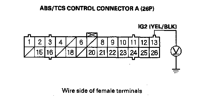
16. Measure the voltage between ABS/TCS control unit connector A (26P) terminal No. 13 and body ground.
Is there battery voltage?
YES - Go to step 17.
NO - Repair open in the wire between the R/C MIRROR (7.5 A) fuse and the ABS/TCS control unit.
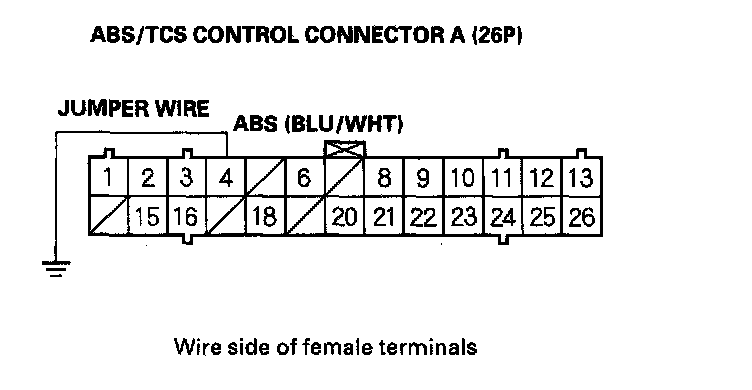
17. Connect ABS/TCS control unit connector A (26P) terminal No. 4 to body ground with a jumper wire.
Does the ABS indicator go off?
YES - Check for loose ABS/TCS control unit connectors. If necessary, substitute a known-good ABS/TCS control unit, and rechecked
NO - Go to step 18.
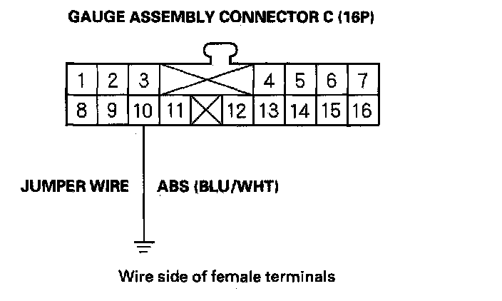
18. Connect the gauge assembly connector C (16P) terminal No. 10 to body ground with a jumper wire.
Does the ABS indicator go off?
YES - Repair open in the wire between the gauge assembly and the ABS/TCS control unit.
NO - Replace the printed circuit board in the gauge assembly.