Idle Speed/Throttle Actuator - Electronic: Testing and Inspection
Idle Speed Control (ISC) System:
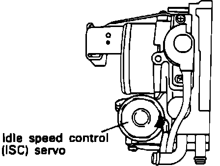
Idle Speed Control Servo (Stepper Motor):
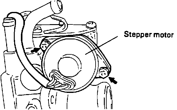
To test the Idle Speed Control (ISC) Servo (also called a Stepper Motor), located on the throttle body, proceed as follows.
ISC Motor Connector Location:
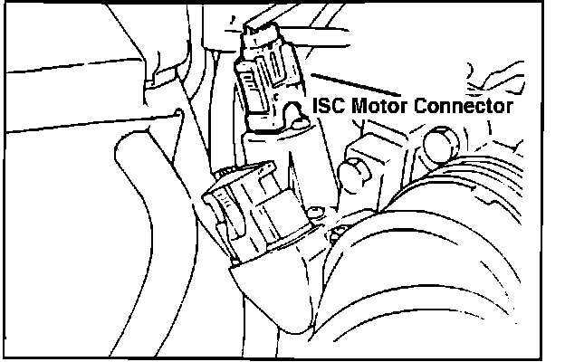
1. Disconnect the ISC connector.
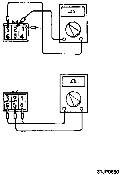
2. Check the continuity of the respective terminals of the ISC connector.
Standard Values:
Terminal 2 to terminals 3 and 1....28 to 33 ohm @ 68~F
Terminal 5 to terminals 4 and 6....28 to 33 ohm @ 68~F
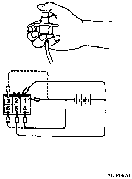
3. Connect 6V DC (four dry cells) to the respective ISC connector terminals to insure that the ISC servo operates.
CAUTION: Apply only a 6V DC or lower voltage. Application of higher voltage could cause damage to the stepper motor.
4. Connect the power supply positive lead to both terminals 2 and 5, then apply voltage as follows:
a. Apply the negative power supply lead to both terminals 1 and 4.
b. Apply the negative power supply lead to both terminals 3 and 4.
c. Apply the negative power supply lead to both terminals 3 and 6.
d. Apply the negative power supply lead to both terminals 1 and 6.
e. Apply the negative power supply lead to both terminals 1 and 4.
5. If movement occurs during each step of the inspection, then the stepper motor considered to be serviceable.