Shift Lever Assembly
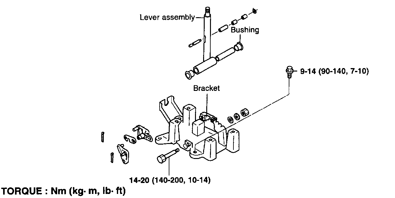
INSPECTION
- Check the detent place for wear.
- Check the bushing for wear or damage.
- Check the spring for damage or deterioration.
- Check the pin at the end of the rod assembly for wear.
SHIFT LOCK DEVICE INSTALLATION INSTRUCTIONS
NOTE: When servicing the shift lock device, follow the service instructions and procedures described in order to operate it normally.
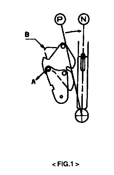
1. Procedure to install the lock cam.
1) Move the P-lock cam to direction "A" and hold it with hand, (Refer to figure 1).
2) Check that key lock cam is located at "B" by detent pin. (Refer to figure 1,2).
2. Procedure for adjusting shift lock and key lock cable
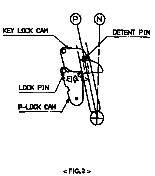
1) Check that each lock cam is located in position as figure 2.
2) Install shift lock cable and key lock cable in position.
In this case, key lock cable must be fixed to key cylinder and shift lock cable must be fixed to brake pedal in position.
3) Temporarily install each cable to A/T lever assembly as shown in figure 3 . Securely insert cable end into fixing pin of each cam.
4) Keep the gap of 2 - 4 mm between key lock cam and P-lock cam to eliminate the cable slack by pulling the shift lock cable slightly in the direction of "E" (Refer to figure 3).
CAUTION: If the gap is not maintained between 2 and 4mm, the brake pedal should be depressed more than required when operating the push button of the shift lever.
5) After checking that a portion of cable end touches cable fixing pin of P-lock cam, fix shift lock cable to A/T lever with nut and fix the shift lock cable end with the washer and snap pin (Refer to figure 4).
6) Slightly push key lock cam in the direction of "Q".
7) Performing the work of 6), slightly pull the key lock cable in the direction of "G" to stretch the cable tight and then fix it with a nut (Refer to figure 3,4).
8) Be sure to check whether the key lock cable is inserted into the fixing pin of key lock cam, and then fix it with the washer and snap pin.
At this time, check if the P-lock cam is fixed to the shift lock cable as shown in the figure 4.
3. Checking that procedure for installing the shift lock is correct
1) When the brake pedal is not depressed, push button of the shift lever at "P" position cannot be operated. (Shift lever cannot be shifted at the other positions from "P").
Push button can be operated at the other positions except.1p...
2) When brake pedal stroke is 15 - 25 mm (with shift lever at "P" position), push button should be operated without catching and shift lever can be shifted smoothly to other from "P".
3) When brake pedal is not depressed, shift lever should be shifted smoothly to "P" position from other positions.
4) Brake pedal must be operated smoothly without catching at all positions.
5) When the ignition key is at "LOCK" position, although brake pedal is depressed, the push button should be operated.
6) Ignition key must not be turned to "LOCK" position except "P" position.
7) If shift lever is shifted to "P" position, ignition key must be turned to "LOCK" position smoothly.
4. Caution in service
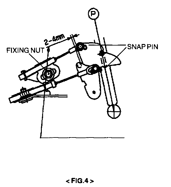
1) Keep the gap of 2 - 4 mm between key lock cam and P-lock cam by pulling the shift lock cable in the direction of "E" slightly and then fix the cable with a nut.
After this, work be sure to check that the gap is within 24 mm.
NOTE: If the gap is not maintained between 2 and 4 mm, the brake pedal should be depressed more than required in order to shift the lever from "P" to other positions even though the brake pedal is depressed.
2) To be sure that the key lock cable slack should be eliminated.
NOTE: If slack of the key lock cable is not eliminated, the ignition key cannot be removed from the key cylinder and shift lever can be shifted from "P" to other positions although the key is in the "LOCK" position.
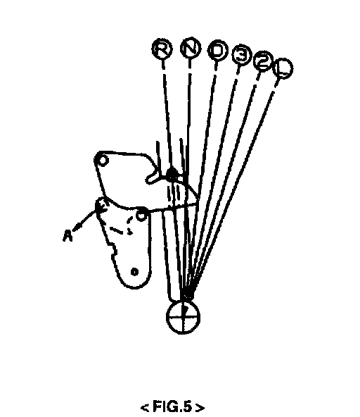
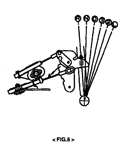
3) Before and after the relating work, the key lock cam and P-lock cam should not be in the same condition as the figure 5 and 6.
NOTE:
When the key lock cam and P - lock cam are in the same condition as the figure 5 and 6, shifting the shift lever from D, 3, 2, L positions to P, R, N by force may cause a malfunction of relating parts.
Under the condition in the figure 5, shift the shift lever from D, 3, 2, L to P, R, N after rotating the P - lock cam in the direction of "A".
Under the condition in the figure 6, shift the shift lever from D, 3, 2, L to P, R, N after rotating the P - lock cam in the direction of "A" depressing the brake pedal.
KEY INTER LOCK DEVICE INSTALLATION INSTRUCTIONS
It is expected that the ignition key may not be removed from the key cylinder due to misassembly of the key inter lock cable.
To prevent above problem, keep the following installation instructions for key inter lock cable when servicing.
1. Assembly of key inter lock cable and ignition lock
1) Ignition lock is in the state assembled with the steering column.
Set the ignition lock to the lock position.
2) Assemble the key inter lock cable and the ignition lock with the set screw.
2. Assembly of key inter lock cable and shift lever.
1) Set the shift lever to parking position.
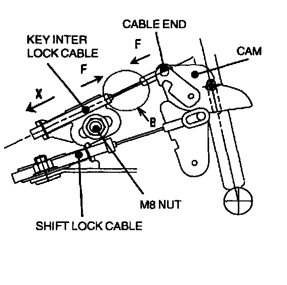
2) After setting the key inter lock cable as shown in the figure 7, temporarily assemble the key inter lock cable with a M8 nut enough to move the key inter lock cable plate by its spring force.
3) Holding the cable and the key inter lock cable plate, push them into the direction of "F" so as not to create any bending or slack on the "B" point of the key inter lock cable.
NOTE:
Do not pull the cable in the direction of "X" holding the cable to remove the slack.
This may cause key not to remove from the key cylinder.
4) Tighten the key inter lock cable installed temporarily firmly with a M8 nut.