Radio - Poor AM Reception
Group: ELECTRICALNumber: 01-90-005
Date: MAY, 2001
Model: 2001 XG300
Subject:
2001 XG300 IN-GLASS ANTENNA AMPLIFIER WEAK AM RECEPTION
DESCRIPTION:
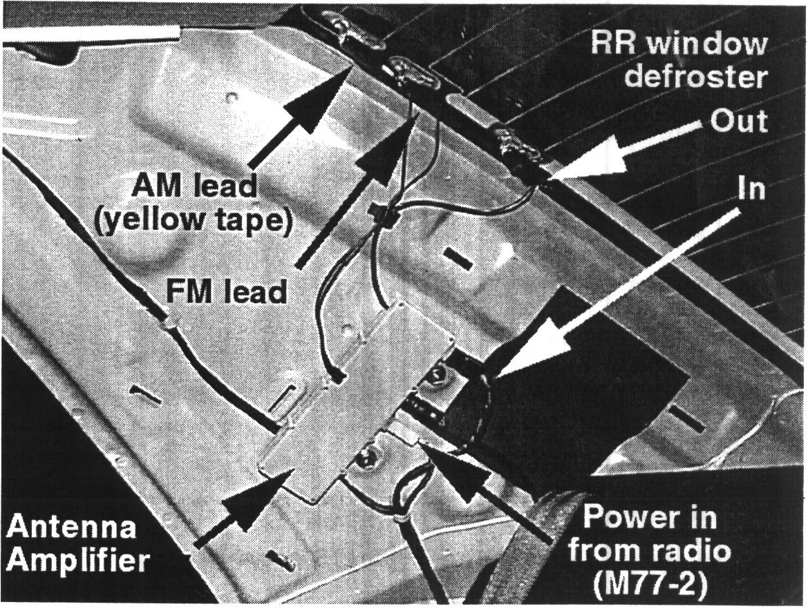
The rear window glass on the XG300 model contains specific AM/FM antenna grids. If the leads to the antenna amplifier from these grids are incorrectly reversed, the AM reception will be poor.
NOTE:
The antenna amplifier is powered ONLY when the radio is on, it is NOT powered when the CD or Cassette player is in use.
NOTE:
The antenna amplifier and the antenna grids in the rear window together form the "Diversity Antenna" as shown in the ETM under "Audio System".
NOTE:
Right rear "C" pillar with interior trim panel removed.
DIAGNOSTIC PROCEDURE:
Make sure the radio turns on, and that it operates in the CD mode. Verify the customer's description of the condition may be duplicated, and that it is not present in another XG300 under the same conditions with the same model radio that operates properly.
Access the antenna amplifier by removing the RH 'C' pillar trim. First, loosen the door opening molding to get access to the back of the RH 'C' pillar trim, then carefully pop the clips out of the 'C' pillar. Work from the top clips to the bottom, then remove the RH 'C' pillar trim.
^ If the AM mode does not operate but the FM mode does, check the connections between the antenna amplifier and the rear window in-glass antennas. You MUST make sure the lead with the yellow tape is connected to the top grid.
^ If neither AM nor FM modes operate on the radio, check that the power and ground have at least 12V between them by using a test lamp when the radio is on in the AM or FM modes. Other checks include checking the integrity of the antenna feeder cable, and the connections between the antenna amplifier and the rear window in-glass antennas.
NOTE:
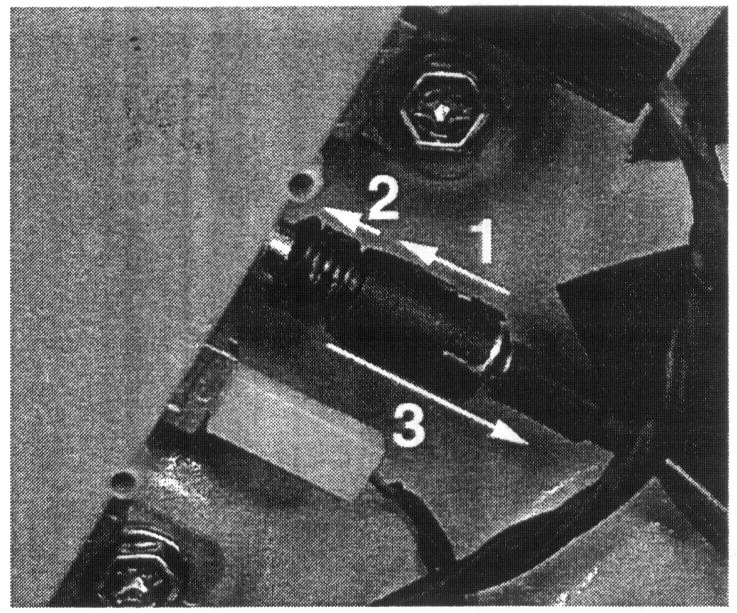
The antenna lead is clipped to the antenna amplifier. Slide the antenna lead up, then slide the collar up to release the lead. See photo for sequence.
NOTE:
When testing the antenna feeder cable integrity, be sure not to expand the female receptacle at the rear of the vehicle. The resistance from end to end should not exceed 3 ohms; the resistance between the inner wire and the outer shielding wire should be infinite (greater than 1M ohms).
WARRANTY INFORMATION
Normal warranty procedures apply. Refer to the LTS manual for details.