P2066
This article has been updated by technical service bulletin 06-90-019 dated July 2006.
The dual fuel level sender diagnostic trouble codes P2065, P2066, P2067, and P2068 were inadvertently omitted from the 2006 Azera Shop manual. Each code's related set criteria and diagnostic procedure is provided in this bulletin.
P2066 - FUEL LEVEL SENSOR OBD CONSUMPTION ERROR
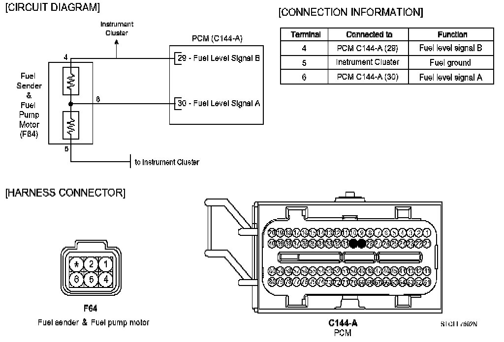
Additional wiring schematic information for the dual fuel level sender system can be obtained from TSB 06-90-018.
DTC P2066 Fuel Level Sensor "B" Consumption Error
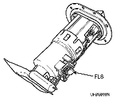
Component Location:
General Description
The Fuel Level Sensor (FLS) measures fuel level in the fuel tank and its information is used by the PCM to monitor the condition of the EVAP canister purge system (i.e. leak detection). If the fuel level sensor reads too high of a signal, too low (stuck), or if the difference between the voltage of the fuel level sensor and the voltage deviation of the fuel level sensors exceeds a preset value while driving, the PCM will interpret this as a fault.
DTC Description
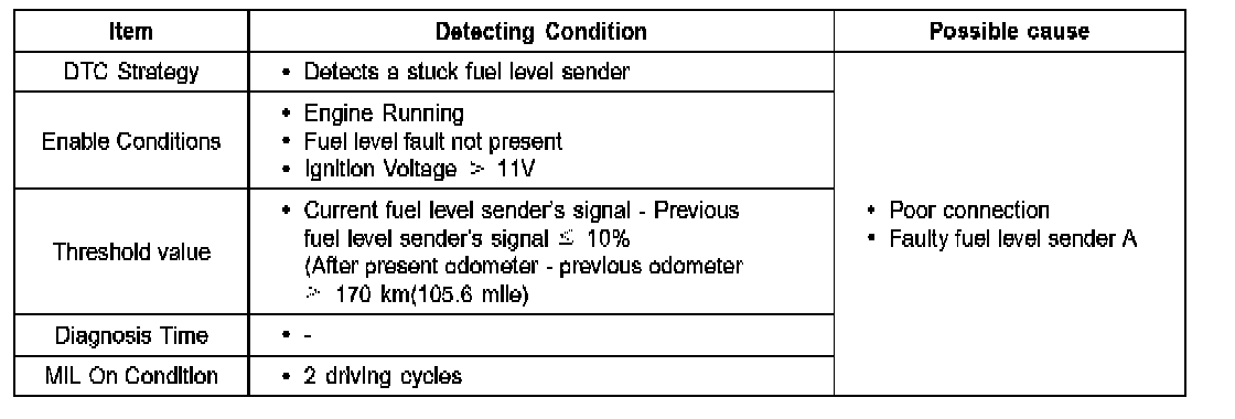
Checking fuel level change under detecting condition, if the fuel level difference between the current reading and previous reading is lower than 10%, while the odometer difference between the present and previous readings is higher than 170km, the PCM will set P2066. MIL (Malfunction Indication Lamp) will illuminate if the condition lasts two consecutive drive cycle.
DTC Detecting Conditions:
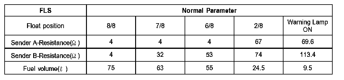
Specifications:
Schematic Diagram:
Monitor Scantool Data
1. Check DTC Status
1) Connect scantool to Data Link Connector (DLC).
2) IG "ON".
F4 DTAL:
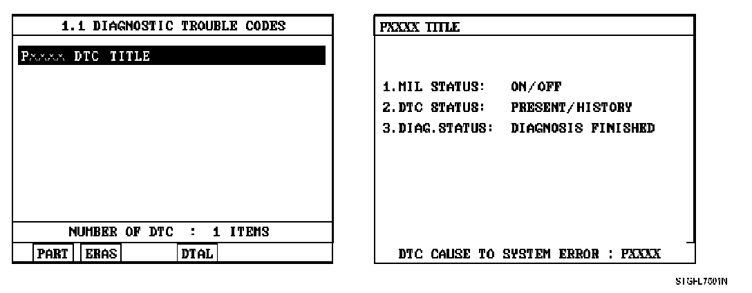
3) Select "Diagnostic Trouble Codes (DTCs)" mode, and then Press F4 (DTAL) to check DTC's information from the DTC's menu.
4) Read "DTC Status" parameter.
5) Is parameter displayed "Present fault"?
YES
Go to "Terminal and Connector Inspection" procedure.
NO
Fault is intermittent caused by PCM memory not being cleared after a repair. Erase DTC and drive the vehicle to satisfy the enable condition then go to "Component Inspection" procedure.
Terminal And Connector Inspection
1. Many malfunctions in the electrical system are caused by harness and terminal issues. Faults can also be caused by interference from other electrical systems, and mechanical or chemical damage.
2. Thoroughly check connectors for looseness, poor connection, bending, corrosion, contamination, deterioration, or damage.
3. Has a problem been found?
YES
Repair as necessary and go to "Verification of Vehicle Repair" procedure
NO
Go to "Component Inspection" procedure
Component Inspection
1. Ignition "OFF"
2. Disconnect Fuel Sender & Fuel Pump Motor connector and remove Fuel sender from fuel tank.
Resistance Check:
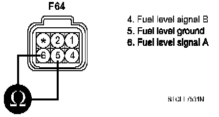
3. Measure resistance between terminal 5 and 6 of Fuel Sender & Fuel pump motor. (Component Side)
4. Does the resistance of FLS change as lifting up and down the fuel level float ?
YES
Fault is intermittent, possibly caused by the float binding on some object. Thoroughly check for any foreign objects impeding float movement. Erase DTC and drive the vehicle to satisfy the enable condition then go to "Verification of Vehicle Repair" procedure.
NO
Substitute with a known-good Fuel Level Sender and check for proper operation. If the problem is corrected, replace Fuel Level Sender and go to "Verification of Vehicle Repair" procedure.
Verification Of Vehicle Repair
After a repair, it is essential to verify that the fault has been corrected.
1. Connect scan tool and select "Diagnostic Trouble Codes (DTCs)" mode
2. Press F4 (DTAL) and confirm that "DTC Readiness Flag" indicates "Complete".
If not, drive the vehicle within conditions noted in the freeze frame data or enable conditions.
3. Read "DTC Status" parameter
4. Is parameter displayed "History (Not Present) fault"?
YES
System performing to specification at this time.
Clear the DTC
NO
Go to the applicable troubleshooting procedure.