4X4 System - Binding/Crow Hop Sensation on Turns
TSB SB04-05-S005Shudder, Rocking Motion, Binding, Feels Like Vehicle is Stuck in
4WD (Crow Hop) When Turning at Low Speeds
ISSUE DATE: MAY 2004
Affected Vehicles
2003 Isuzu Ascender models equipped with 4WD.
Service Information
Condition:
Some customers may comment that when turning, the vehicle feels like it is binding, or the vehicle feels like it is stuck in 4WD (crow hop), or that the 4WD system is not working correctly, a shudder type sensation is felt.
Possible Cause:
This intermittent condition may be difficult to duplicate, the potential is only present in the Auto Mode of the transfer case.
Correction:
Replace the Transfer Case Encoder (Sensor) and reprogram TCCM. DO NOT REPLACE THE TRANSFER CASE MOTOR.
Service Procedure
NOTE:
It is extremely important to check all of the tires before repairs are attempted for these types of customer concerns. Mismatched tires may cause these types of customer concerns. Inspect the tires in the following areas.
1. Ensure that the tires are inflated to the recommended tire pressure as listed on the tire placard on the driver's door.
2. Use a tire tread depth gauge to determine the tread depth. The tire tread depth must be nearly equal on all four corners of the vehicle.
3. Ensure that the tires are all the same brand, size, and tread design.
1. Place the 4WD selector switch in the 2 HI position.
2. Raise the vehicle.
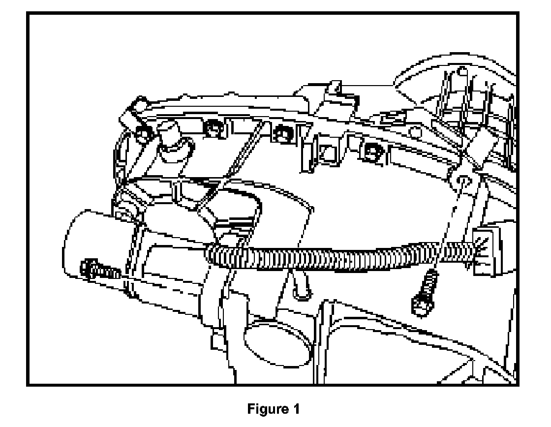
3. Disconnect the wiring harness connector at the top of the transfer case (see figure 1).
4. Remove the Actuator Assembly Transfer Case Four Wheel Drive (Motor) mounting bolts.
5. Remove the motor from the transfer case and set aside.
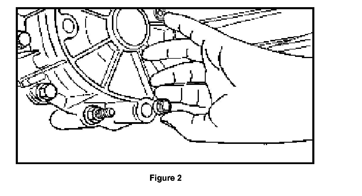
6. Position an oil drain container into position under the transfer case drain plug. Remove the drain plug and allow the transfer case to drain (see figure 2).
7. Position the motor on a workbench and you will see four retaining tabs that retain the insulator to the motor. Release the tabs to allow removal and discard the insulator.
8. Lift/pry the sensor from the motor shaft and disconnect the sensor from the wiring harness. Look at the motor where you just removed the sensor, you will notice the "Hex" in the casting where the new sensor will seat when properly installed.
NOTE:
Gently lift and tilt the sensor toward the wiring connector wiring to disconnect it. You will notice the two wires to the motor. The red and black wires go to an internal connector within the motor housing. The black plastic connector for these wires does not have a locking tab and is easily disturbed.
9. Connect the wiring harness to the sensor.
10. Gently insert a suitable tool along side the red and black wires and press down on the black plastic connector to ensure the connector is in the proper position.
11. Properly align the key way of the sensor on the shaft and install the sensor. Ensure that the hex on the sensor fits in the hex of the casting.
12. Install the new insulator assembly.
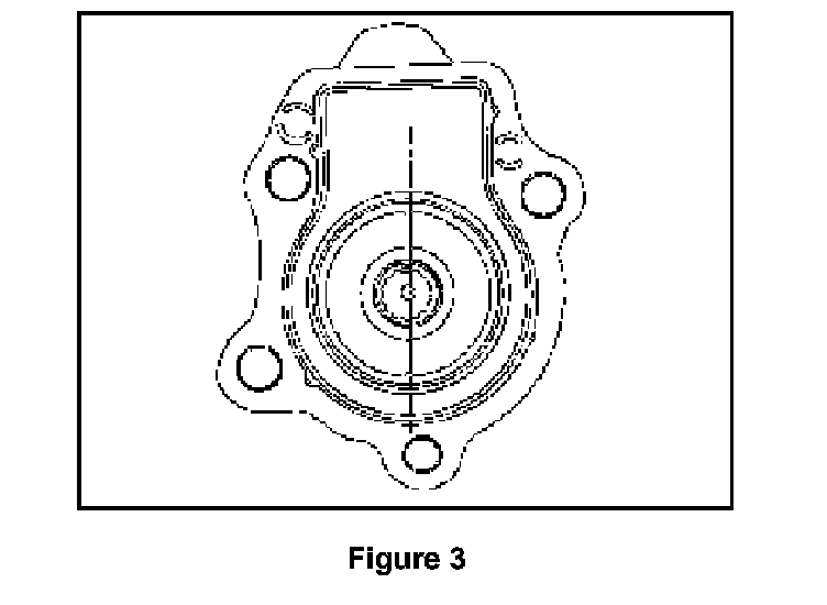
13. Inspect the positioning of the insulator and the motor shaft. If necessary to align them as shown, perform the following steps (see figure 3).
a. Connect a fused jumper to the transfer case encoder motor connector red wire and the other end to a positive battery terminal.
b. Connect another jumper to the transfer case encoder motor connector black wire and shortly touch the other end of this wire to the ground terminal of a battery. This will cause the motor shaft to turn to allow alignment as shown (see figure 3).
14. Position the motor to the transfer case and install the retainers, tighten the bolts to 16 N.m (12 lb ft).
NOTE:
Inspect the encoder motor attachment face for the presence of the two (2) locating sleeves. If missing from the encoder motor, they need to be retrieved from the transfer case and reinstalled into the encoder motor before installation.
15. Apply pipe sealant, P/N 8-12346-004-0 or equivalent, to the drain plug threads. Install the transfer case drain plug, tighten the plug to 27 N.m (20 lb ft).
16. Refill the transfer case with 1.8 L (2 qts) of Auto Trac II Transfer case lubricant, P/N 8-12378-508-0.
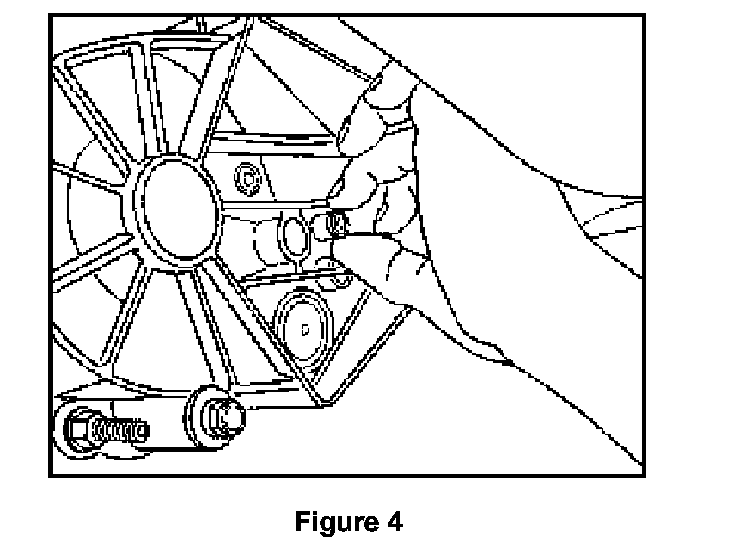
17. Apply pipe sealant, P/N 8-12346-004-0 or equivalent, to the fill plug threads. Install the fill plug. Tighten the plug to 27 N.m (20 lb ft) (see figure 4).
18. Lower the vehicle.
19. Connect the Tech 2 and use SPS reprogramming to reprogram the transfer case control module (TCCM) with ITCS CD # 29 or later.
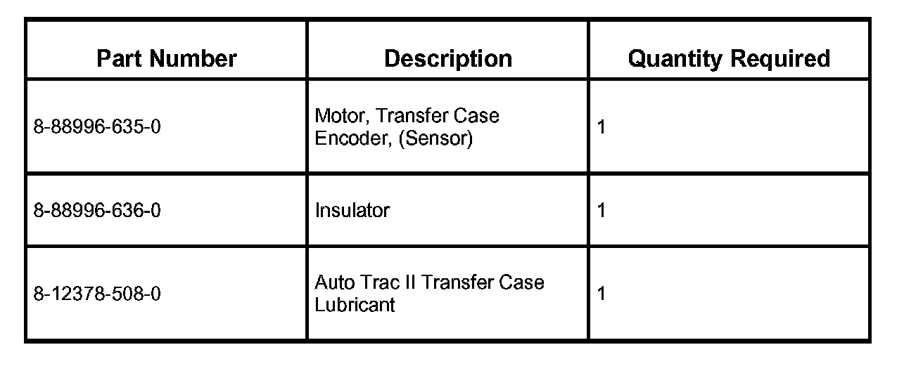
Parts Information
Warranty Claim Information
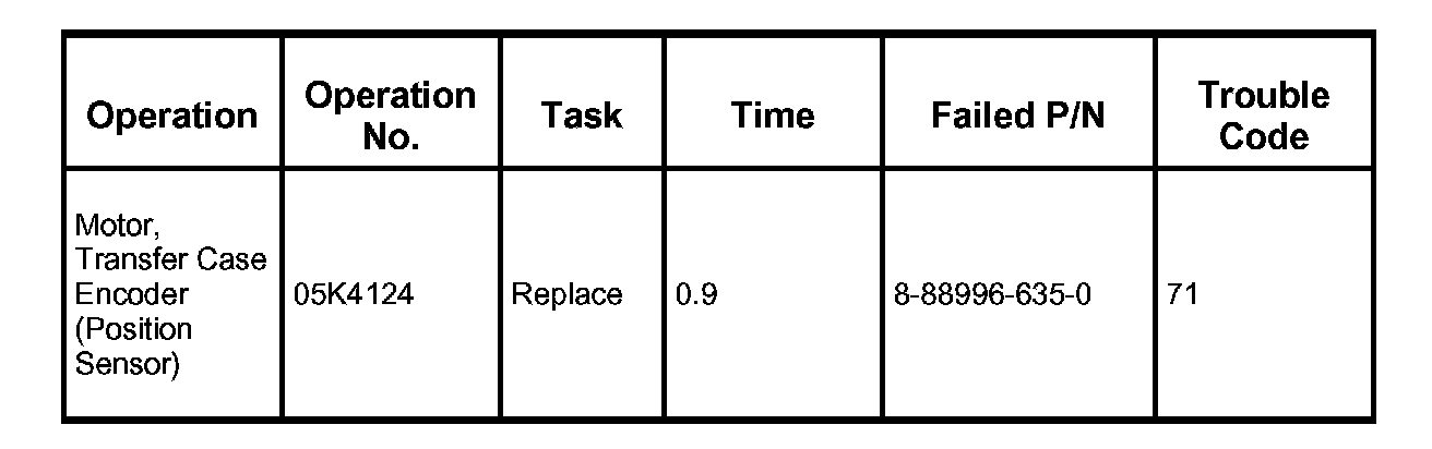
Use the following labor operations:
NOTE:
1. Labor Time includes administrative time allowance.
2. Always refer to the Isuzu Service Policy Procedure Manual for specific details on warranty coverage and policies.
3. Information released on paper and electronic format prior to bulletin release cannot be updated.

Disclaimer