DTC 34
Fig. 76 EGR temperature sensor resistance value chart.:
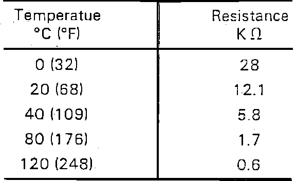
1. Remove EGR sensor, place in water and test sensor as follows:
a. Disconnect sensor electrical connector, then measure resistance across sensor terminals and compare with specifications in chart, Fig. 76.
b. If measured resistance is not as specified in chart, replace EGR sensor.
Fig. 77 EGR temperature sensor circuit identification.:
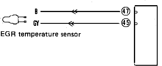
Fig. 79 EGR temperature sensor circuit resistance value chart.:
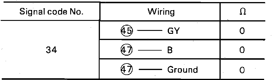
2. Inspect EGR sensor wiring as shown in Fig. 77, then compare with specifications in chart, Fig. 79
3. If measured resistance is not as specified in chart, repair or replace faulty wires.