Campaign - Coolant Hose Rerouting/Replacement
XJ303-S712DATE 08/03
XJ range
MODEL
2004 MY
XJR
VIN
Specific VINs
Coolant Hose - Incorrect Routing - Service Action S 712
Issue:
In-house quality inspections have established that on some 2004 MY XJ Range supercharged vehicles listed in this bulletin, the coolant hose from the thermostat housing to the auxiliary coolant pump may have been incorrectly routed in production, potentially causing the hose to touch the supercharger drive belt and wear through.
Action:
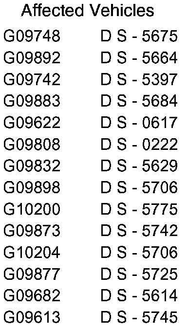
Affected vehicles (see VIN list) should have the coolant hose inspected for the correct routing/damage. Should damage to the coolant hose be evident, the coolant hose must be replaced.
This Service Action should be carried out prior to handover to the customer.
WORKSHOP PROCEDURE
1. Open hood.
2. Install fender protection covers.
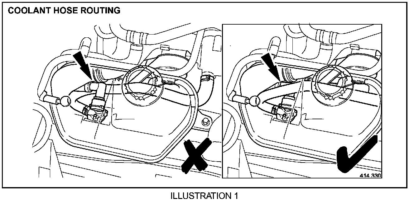
3. Check for correct/incorrect routing of hose - Illustration 1. If the hose routing is correct, as shown in Illustration 1 and identified with a check mark, no further action is required. If the hose routing is incorrect, as shown in Illustration 1 and identified with an X, continue with the workshop procedure from step 4.
Warning:
Never remove the coolant pressure cap under any circumstances while the engine is operating. Failure to follow this instruction may result in personal injury.
To avoid having scalding hot coolant or steam blow out of the cooling system, use extreme care when removing the coolant pressure cap from a hot cooling system. Wait until the engine has cooled, then wrap a thick cloth around the coolant pressure cap and turn it slowly until the pressure begins to release. Step back while the pressure is released from the system. When certain all the pressure has been released (still with a cloth) turn and remove the coolant pressure cap from the coolant expansion tank. Failure to follow these instructions may result in personal injury
Warning:
To avoid the possibility of personal injury, do not operate the engine with the hood open until the fan blades have been examined for cracks and separation. Failure to follow this instruction may result in personal injury
Warning:
Remove fuse 14 from the engine compartment fuse box prior to performing any under hood service in the area of the cooling fan when the engine is hot, since the cooling fan motor could operate if the engine has been switched off. Failure to follow this instruction may result in personal injury
Caution:
The engine cooling system must be maintained with the correct concentration and type of anti-freeze solution to prevent corrosion and frost damage.
Caution:
Never remove the coolant pressure cap under any circumstances while the engine is operating. Failure to follow this instruction may result in damage to the engine.
4. Remove coolant reservoir cap.
5. Raise the vehicle on a ramp.
6. Remove radiator splash shield. See Workshop Manual JTIS CD ROM, section: 501-02.
7. Remove air deflector. See Workshop Manual JTIS CD ROM, section: 501-02.
8. Remove the radiator lower cowl.
9. Drain coolant from the radiator into a clean container for reuse.
10. Reinstall radiator lower cowl.
11. Reinstall air deflector. See Workshop Manual JTIS CD ROM, section: 501-02.
12. Reinstall radiator splash shield. See Workshop Manual JTIS CD ROM, section: 501-02.
13. Lower vehicle on ramp.
14. Remove engine cover.
15. Remove air filter outlet tube. See Workshop Manual JTIS CD ROM, section: 303-12B.
16. Check incorrectly routed hose for damage - if damage is evident, proceed with step 36 to 59 of this workshop procedure. If no damage is evident continue with this procedure to step 35.
17. Undo and remove coolant reservoir securing bolt.
18. Displace coolant reservoir and reposition for access.
19. Reposition incorrectly routed hose securing clip along the hose at the thermostat housing end.
20. Place absorbent cloth under thermostat housing.
Note:
It is important that the drive belts or pulleys do not come into contact with any coolant.
21. Disconnect the hose from the thermostat housing stub pipe.
22. Install suitable tight fitting blanking plugs to the hose and stub pipe.
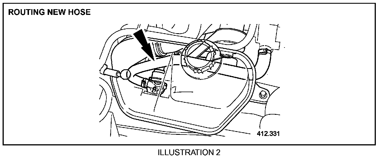
23. Reroute hose. Illustration 2.
24. Displace and remove blanking plugs from the hose and stub pipe.
25. Reconnect hose to stub pipe.
26. Remove absorbent cloth from under thermostat housing stub pipe.
27. Reposition securing clip along hose at thermostat housing end.
28. Reposition and align coolant reservoir to the correct position.
29. Install and fully tighten coolant reservoir securing bolt.
30. Reinstall air filter outlet tube. See Workshop Manual JTIS CD ROM, section: 303-12B.
31. Reinstall engine cover.
32. Refill coolant system with original coolant. See Workshop Manual JTIS CD ROM, section: 303-03B.
Note:
Torque figure for expansion tank bleed renew should be 3 Nm.
33. Install and fully tighten coolant reservoir filler cap.
34. Remove fender protection covers.
35. Close hood.
36. Remove expansion tank for access to damage hose. See Workshop Manual JTIS CD ROM, section: 303-03A.
37. Reposition incorrectly routed hose securing the clip along the hose at the thermostat housing end.
38. Place absorbent cloth under thermostat housing.
Note:
It is important that the drive belts or pulleys do not come into contact with any coolant.
39. Disconnect the hose from the thermostat housing stub pipe.
40. Install suitable tight fitting blanking plugs to the hose and stub pipe.
41. Reposition hose securing clip at auxiliary coolant pump end.
42. Place absorbent cloth around the pump.
Note:
It is important that the drive belts or pulleys do not come into contact with any coolant.
43. Disconnect the hose from the pump and install suitable tight fitting blanking plug to the hose.
44. Remove the hose from the vehicle.
45. Route new hose. Illustration 2.
46. Align and push fully home new hose to pump.
47. Reposition securing clip along hose at pump end.
48. Remove absorbent cloth from around the pump.
49. Displace and remove the blanking plug from the thermostat housing stub pipe.
50. Reconnect hose to stub pipe.
51. Remove absorbent cloth from under thermostat housing stub pipe.
52. Reposition securing clip along hose at thermostat housing end.
53. Reinstall coolant expansion tank. See Workshop Manual JTIS CD ROM, section: 303-03A.
54. Reinstall air filter outlet tube. See Workshop Manual JTIS CD ROM, section: 303-12B.
55. Reinstall engine cover.
56. Refill coolant system with original coolant. See Workshop Manual JTIS CD ROM, section: 303-03B.
Note:
Torque figure for expansion tank bleed renew should be 3 Nm.
57. Install and fully tighten coolant reservoir filler cap.
58. Remove fender protection covers.
59. Close hood.

Parts Information
Warranty Information:
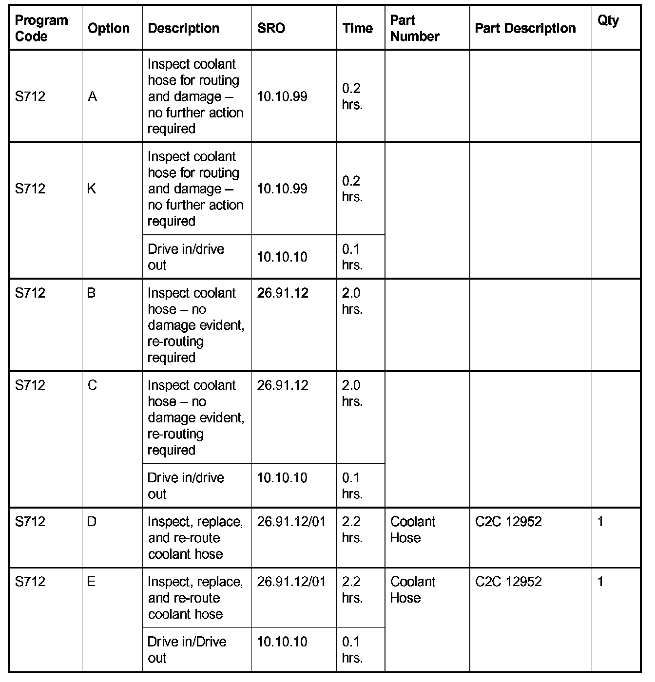
Warranty claims should be submitted quoting program code S712 together with the relevant option code from the table. This will result in payment of the appropriate labor time and any parts, as necessary.
The options for the drive in/drive out allowance should only be claimed if the vehicle is brought back into the workshop for this action alone to be undertaken.
The SROs and parts listed are included for information only There will be no requirement to enter the SROs or parts onto the claim.
NOTE:
Always perform a DDW claim search first to determine whether this service action has been performed on this vehicle. The warranty selection under the vehicle inquiry will give a listing of all claims against the vehicle. If this service action number appears in the program code field, do not perform this service action.