A/C - System Flushing Procedure After Compressor R and R
XJ412-01XJ range
DATE: 02/05
MODEL:
2004 MY-ON
XJ range
VIN:
G00001-ON
Air Conditioning (A/C) System - Flushing - Revised Procedure
Issue:
This Technical Bulletin has been issued to inform the dealer network of a new A/C system flushing procedure following a major A/C compressor failure (debris has entered the A/C system).
Action:
When installing a new A/C compressor a new A/C system flushing procedure must be carried out. Follow the procedure outlined below
SERVICE INSTRUCTION
Note:
Liquid refrigerant MUST be used to flush the A/C system. The flushing equipment MUST have at least 6 kg of refrigerant to carry out the flushing procedure.
With the A/C compressor already removed as described in GTR section 412-03A, and the vehicle still on the lift:
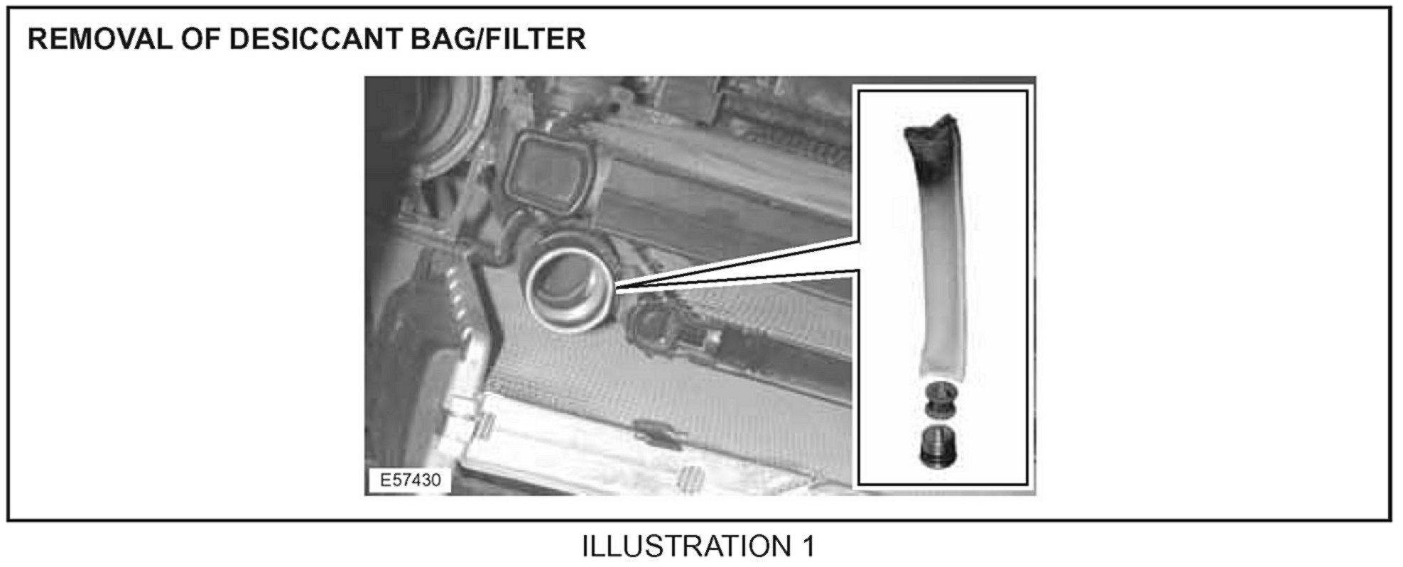
1. Remove the A/C desiccant bag access plug, and remove the A/C desiccant bag and filter (Illustration 1).
2. Record condition of A/C desiccant bag and filter (contamination etc.).
3. Discard the A/C desiccant bag and filter.
4. Install and tighten the A/C desiccant bag access plug.
STAGE ONE BACK FLUSH
Note:
If the original 0-ring seals are in good condition, they may remain in position during flushing procedure only.
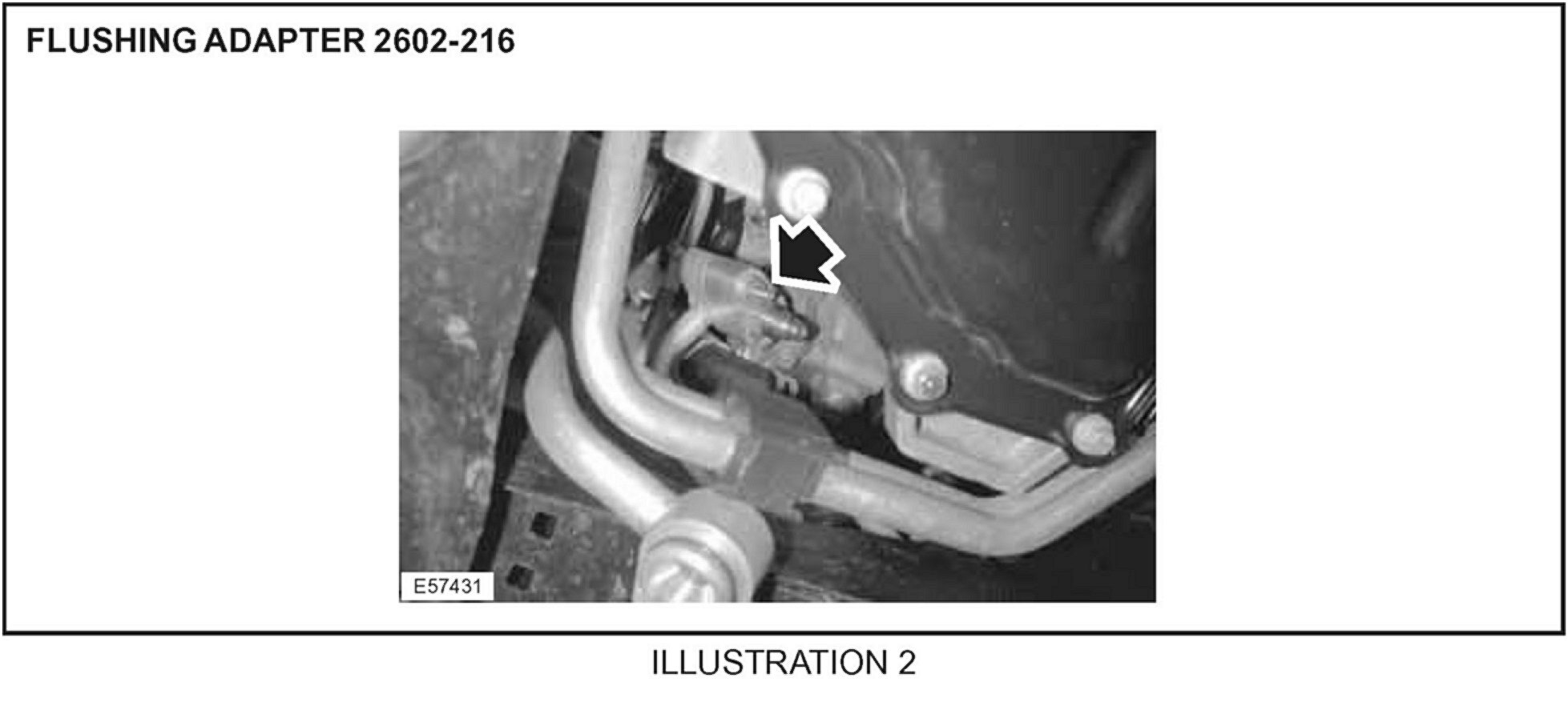
5. Connect flushing equipment adaptor (2602-216) to the end of the A/C compressor discharge pipe (Illustration 2).
6. Install and tighten the adaptor securing nut.
7. Connect flushing equipment inlet pipe to A/C compressor discharge pipe adaptor.
8. Lower lift to a suitable working height.
Note:
With the engine support beam (special tool number 303-021) still in place from removing the A/C compressor (GTR section 412- 03A.)
9. Lower engine support bar hook to lower the engine for access to the central bulkhead area.
10. Remove the A/C inlet and outlet pipes to A/C evaporator unit securing nut.
11. Disconnect the A/C inlet and outlet pipes from the A/C evaporator unit.
12. Reposition the A/C evaporator unit inlet pipe for access to connection.
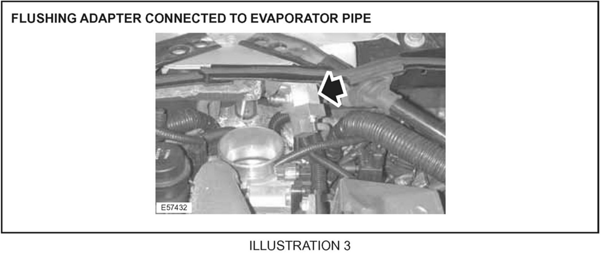
13. Connect the flushing equipment adaptor (2602-214) to the end of the A/C evaporator unit inlet pipe (Illustration 3).
14. Install and tighten the adaptor securing nut.
15. Connect flushing equipment outlet pipe to the A/C evaporator unit inlet pipe adaptor.
Note:
Apply a vacuum to the system to ensure it is leak free.
Note:
Refer to the manufactures guidelines for detailed information.
16. Operate flushing equipment (refrigerant is to be recovered after flushing).
STAGE TWO FORWARD FLUSH:
17. Disconnect the flushing equipment outlet pipe from the A/C evaporator unit inlet pipe adaptor.
18. Loosen adaptor securing nut.
19. Remove the flushing equipment adaptor from the end of the A/C evaporator unit inlet pipe and place aside.
20. Remove and discard the 0-ring seals from the A/C evaporator unit inlet and outlet pipes.
21. Lubricate the new 0-ring seals.
22. Insert the new 0-ring seals in the A/C evaporator unit inlet and outlet pipes.
23. Connect the A/C inlet and outlet pipes to the evaporator unit.
24. Raise engine support bar hook to raise engine to the previous level.
25. Raise lift to a suitable working height.
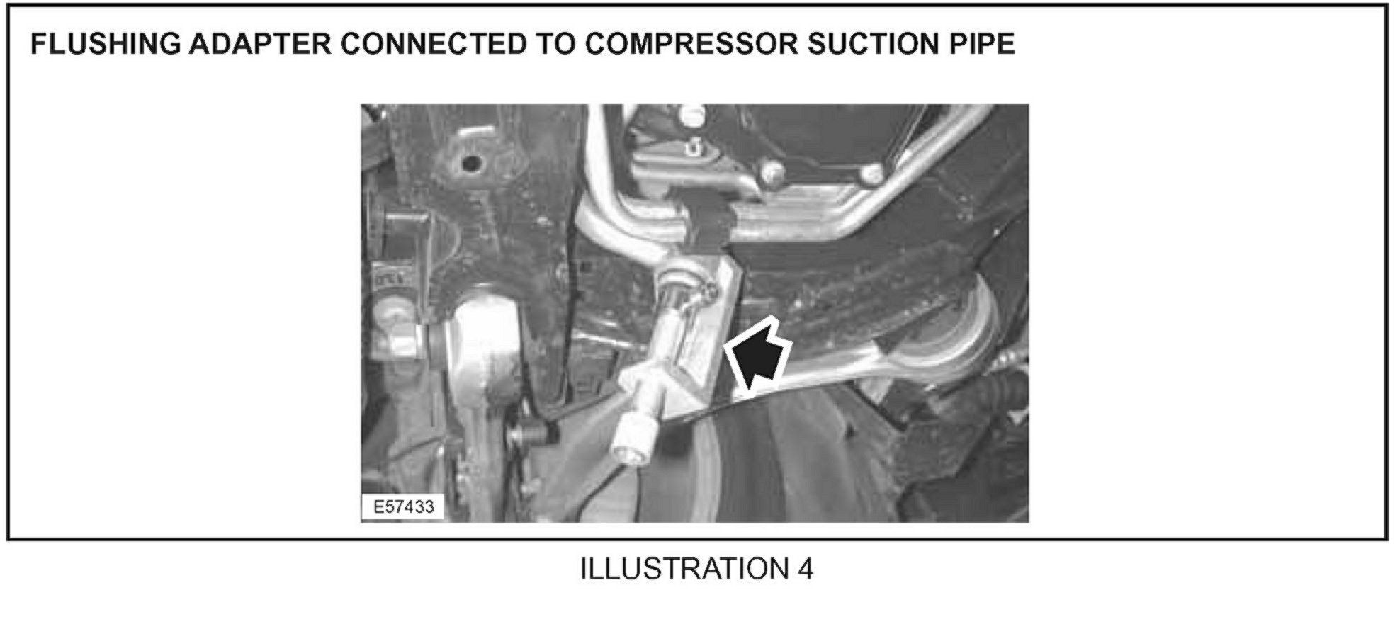
26. Connect flushing equipment adaptor (2602-183 and 2600-123) to the end of the compressor suction pipe (Illustration 4).
27. Tighten adaptor screw.
28. Disconnect flushing equipment pipe from the compressor discharge pipe adaptor.
29. Connect flushing equipment return pipe to compressor suction pipe adaptor.
Note:
Apply a vacuum to the system to ensure it is leak free.
30. Connect flushing equipment outlet pipe to compressor discharge pipe adaptor.
Note:
Refer to the manufacturer's guidelines for detailed information.
31. Operate the flushing equipment (refrigerant must be recovered after flushing).
32. Disconnect flushing equipment return pipe from compressor suction pipe adaptor.
33. Remove the adaptor screw, and place aside.
34. Disconnect flushing equipment outlet pipe from compressor discharge pipe adaptor.
35. Remove the adaptor, and place aside.
Note:
New 0-ring seals must be installed in the compressor suction discharge pipes during compressor renew.
36. Remove the desiccant bag access plug.
Note:
The new desiccant bag contains leak check dye.
37. Install a new desiccant bag.
38. Install new access plug.
39. Install new filter.
40. Install and tighten access plug.
With the compressor installed and with the A/C system charged, proceed as follows:
41. Set all air ducts at the dashboard to open.
42. Switch ignition 'ON'.
43. Set blower to a minimum of 75% of the maximum blower performance.
44. Set control panel to auto low or maximum or maximum cooling performance.
45. Start engine and allow the engine speed to stabilize.
46. With the A/C 'ON', allow the engine to run for two minutes continuously at compressor speed less than 1800 rpm.
Note:
Refer to manufacturer's guidelines for detailed information on flushing equipment maintenance and filter change.
47. After two minutes of compressor operation, the oil distribution in the A/C system is finalized.
Global Technical Reference (GTR) Workshop Manual Information:
Internet access: http://www.jaguartechinfo.com

Parts Information

Warranty Information

Disclaimer