Description
Evaporative Emissions
The atmospheric pressure at the air intake vent of the system is higher than the inlet manifold pressure under all throttled engine running conditions. It is this pressure differential across the system that causes the air to flow through the air intake, through the purge system, and in to the engine.
The ECM (engine control module) waits until the engine is running above 40°C (104°F) coolant temperature with closed loop fuel operational before the purging process is activated. Under these conditions the engine should be running smoothly with no warm up enrichment. The purge valve duty (and flow) is initially ramped slowly because the vapor concentration is unknown (a sudden increase in purge could cause unstable engine running or cause it to stall due to an extremely "rich" air/fuel mixture.). The concentration is then determined from the amount of adjustment that the closed loop fueling is required to make to achieve the target Air Fuel Ratio (AFR). Once the concentration has been determined, the purge flow can be increased rapidly and the injected fuel can be proactively adjusted to compensate for the known purge vapor and the target AFR control is maintained.
When the purging process is active, fresh air is drawn into the charcoal canister via the tank leakage detection valve atmospheric vent connection and its filter on NAS vehicles or, via the vent hose connection and the spider trap on non NAS vehicles.
Tank Leakage Detection
The tank leakage detection system is a legislative requirement for NAS vehicles. The tank leakage detection system periodically checks the EVAP (evaporative emission) system and the fuel tank for leaks when the ignition is switched off. The tank leakage detection system comprises the previously described components of the EVAP (evaporative emission) system with the following additional components; a tank leakage detection pump and a tank leakage detection filter.
To check the fuel tank and the EVAP (evaporative emission) system for leaks, the ECM (engine control module) operates the tank leakage detection pump and monitors the current draw. Initially, the ECM (engine control module) establishes a reference current by pumping air through the reference orifice and back to atmosphere. Once the reference current is determined, the ECM (engine control module) closes the normally open valve which seals the EVAP (evaporative emission) system. The purge valve remains de-energized and is therefore closed. The output from the air pump is diverted from the reference orifice and into the EVAP (evaporative emission) system.
When the normally open valve is closed, the load on the air pump falls to zero. Providing there are no leaks, the air pump will begin to pressurize the EVAP (evaporative emission) system and the load and current draw in the pump increases. By monitoring the rate and level of the current increase, the ECM (engine control module) can determine if there is a leak in the EVAP (evaporative emission) system.
During normal vehicle operation, 15 seconds after the engine has started, the ECM (engine control module) energizes the heating element in the pump to prevent condensation formation and possible incorrect readings. The heater remains energized until either the engine and ignition are off (if no tank leakage detection test is running) or until after the tank leakage detection test is completed.
Leaks are classified as:
- Minor - equivalent to a hole diameter of 0.5 to 1.0 mm (0.02 to 0.04 in)
- Major - equivalent to hole diameter of 1.0 mm (0.04 in) or greater.
The ECM (engine control module) performs a check for major leaks each time the ignition is switched off, providing the following conditions are met:
- The vehicle speed is zero
- The engine speed is zero
- The pressure altitude (70 kPa (10.15 lbf/in2) derived from engine load calculations) is below 3047 m (10000 feet)
- The ambient temperature is between 0 and 40°C (32 and 104°F)
- The charcoal canister load factor is 2.5 or less (where the load factor is a measure, between -1 and +30, of the fuel vapor stored in the charcoal canister. Where -1 is 0% fuel vapor, 0 is stoichiometric fuel vapor level and +30 is 100% saturated with fuel vapor.
- The fuel tank level is valid and between 15 and 85% of nominal capacity
- The engine running time during the previous cycle was more than 10 minutes
- The battery voltage is between 10 and 15 volts
- The last engine off time was more than 180 minutes
- No errors are detected with the EVAP (evaporative emission) components, the ambient air temperature and the fuel level.
NOTE:
A leak test can be performed using the Jaguar approved diagnostic system. This overrides the above conditions and is useful for checking correct system and component operation.
The ECM (engine control module) performs a check for minor leaks after every 2nd major leak check or after refueling is detected.
When the leak check is complete, the ECM (engine control module) stops the tank leakage detection pump and opens (de-energizes) the normally open valve.
If the fuel filler cap is opened or refueling is detected during the leak check, by a sudden drop in the current draw or a rise in the fuel level, the ECM (engine control module) aborts the leak check.
If a leak is detected during the check, the ECM (engine control module) stores an appropriate fault code in its memory. If a leak is detected on two consecutive checks, the ECM (engine control module) illuminates the MIL (malfunction indicator lamp) in the instrument cluster on the next drive cycle.
The duration of a leak check can be between 60 and 600 seconds depending on the results and fuel tank level.
Tank Leakage Detection Pump
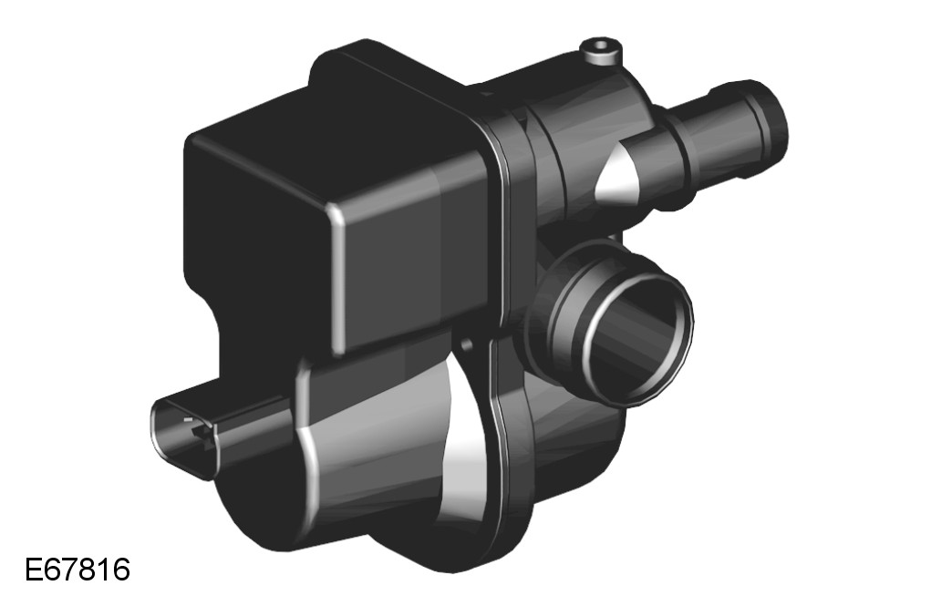
The tank leakage detection pump is connected to the atmospheric vent of the charcoal canister and incorporates a PTC (positive temperature coefficient) heating element, a normally open valve and a reference orifice.
The tank leakage detection filter protects the pump from dust being drawn into the system when the pump is being operated. The filter is located on the fuel filler head and is connected to the tank leakage detection pump by a hose.
The tank leakage detection pump is only operated when the ignition is switched off and is controlled by the ECM (engine control module). The ECM (engine control module) also monitors the electric air pump operation and the normally open valve for faults The tank leakage detection test is performed after the engine has stopped following a 10 minute run, providing that the vehicle fuel tank is between 15 and 85 percent full, the ambient temperature is above 0°C (32°F) and less than 40°C (104°F) and the vehicle was not started for at least 3hrs prior to this run.
The tank leakage detection pump is driven to pressurize the fuel tank and the current is measured with the change-over valve in different states.
A comparison of the current draw in each state indicates the degree of any leak, and the ECM (engine control module) then sets the appropriate DTC (diagnostic trouble code).
Charcoal Cannister
The charcoal canister is located in a central position, forward of the spare wheel. It is attached at the rear with two bolts which screw into the spare wheel carrier. At the front, the canister has two lugs which locate in the parking brake module support bracket.
The canister on ROW vehicles has a capacity of 1400cc (85.4 in3). The canister on NAS vehicles has a capacity of 3000cc (183 in3).
The canister has three ports which allow for the attachment of the atmospheric vent hose, the purge hose and the tank vent hose. On NAS vehicles the atmospheric vent hose connection allows for the attachment of the tank leakage detection pump.
The canister contains a bed of activated charcoal or carbon. The charcoal is produced using special manufacturing techniques to treat the charcoal with oxygen. The oxygen treatment opens up millions of pores between the carbon atoms resulting in a highly porous charcoal with a very large effective surface area which is capable of absorbing large quantities of fuel vapor. Once treated the charcoal is known as 'activated' carbon or charcoal. The charcoal canister on NAS vehicles uses a higher grade charcoal to meet the requirements of LEV2 emission regulations.
Purge Valve
The purge valve is located RH (right-hand) side of the engine, on a bracket which is attached to the water pump. The purge hose is routed from the purge valve to the electric throttle. The purge valve is controlled by the ECM (engine control module) and is operated when engine operating conditions are correct to allow purging of the charcoal canister. The purge valve is a solenoid operated valve which is closed when de-energized.
The purge hose is connected, at the front RH (right-hand) side of the engine, with a quick release coupling to the purge line which runs parallel with the fuel feed line along the top of the fuel tank to the charcoal canister.
The purge hose continues from the purge valve and is routed to a connection on the air intake elbow assembly. The hose is connected to the elbow with a quick release connector.
The purge valve is PWM (pulse width modulation) at 10Hz by the ECM (engine control module). At this high frequency, the pulses of purge gas flow into the inlet manifold in an almost a continuous flow. The valve operates between 7% and 100% duty or mark space ratio (% open time).
On NAS vehicles the system does not include a pressure test point. Pressure testing of the purge valve hose is achieved by disconnecting the purge valve joint on the underside of the vehicle, forward of the fuel tank and connecting a special tool to allow the system to be pressure tested. The test performs a pressure test on the purge hose connection forward of the fuel tank back to the charcoal canister. The special tool is then connected to the purge hose connection forward of the fuel tank to perform a pressure test on the purge hose to the purge valve.