Removal and Replacement
Engine Wiring Harness
Removal
1 Remove the cover and disconnect the battery ground cable. For additional information, refer to Specifications [1][2]Battery
2
WARNING: Do not work on or under a vehicle supported only by a jack. Always support the vehicle on safety stands.
Raise and support the vehicle.
3 Remove the intake air resonator. For additional information, refer to Intake Air Resonator Service and Repair
4 Remove the engine control module (ECM). For additional information, refer to Engine Control Module (ECM) Service and Repair
5 Recover the A/C refrigerant.
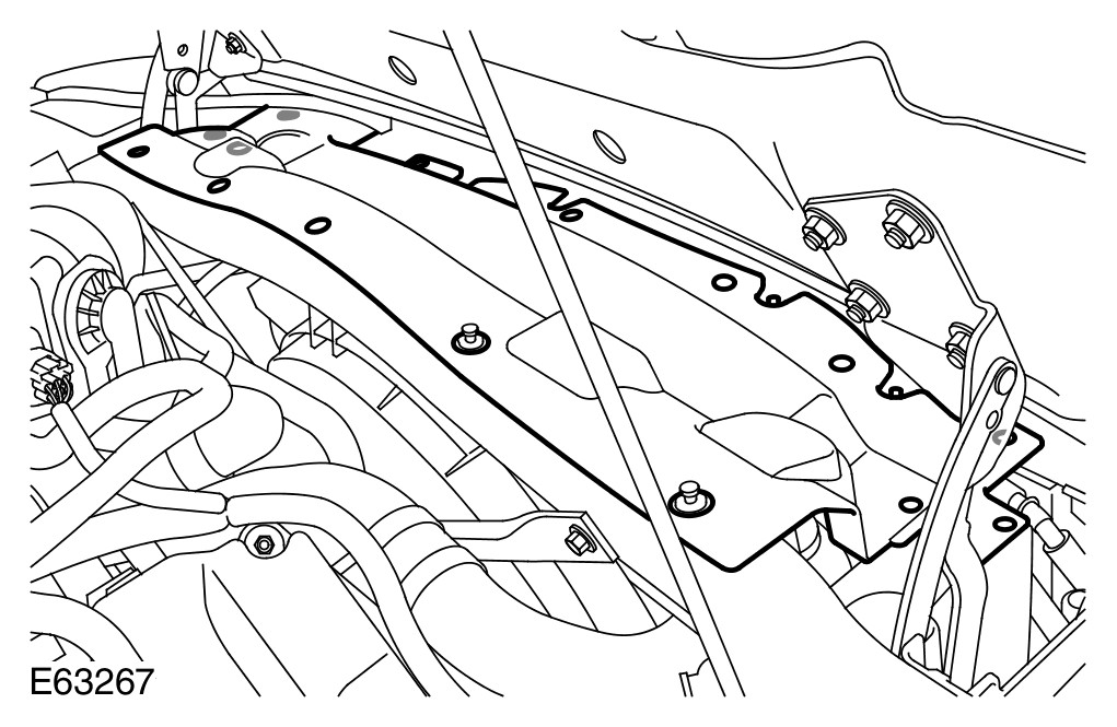
6 Remove the fan cowl.
- Remove the 15 clips.
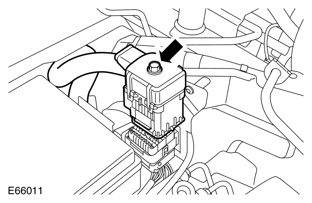
7 Release and disconnect the engine wiring harness electrical connector.
- Fully loosen the bolt.
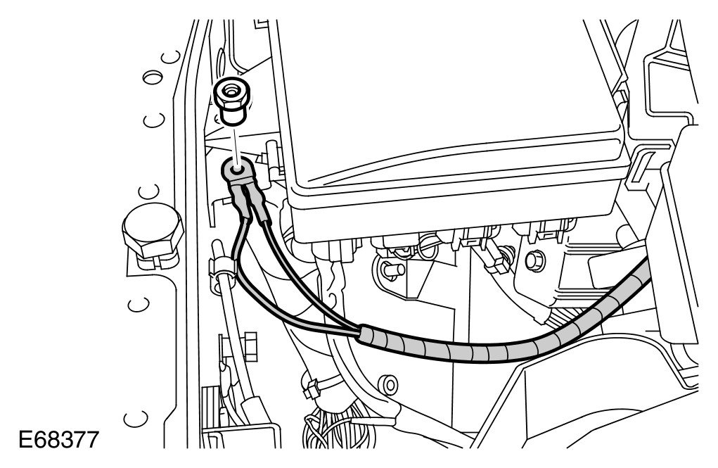
8 Release the ground cable from the power distribution box bracket.
- Remove the nut.
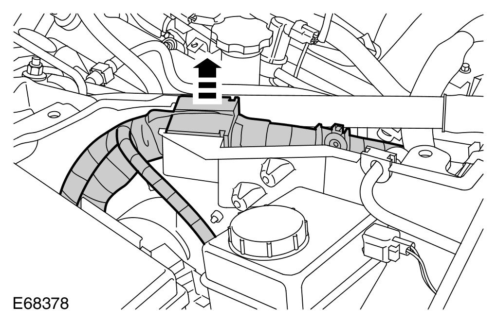
9 Release the engine wiring harness from the engine compartment side wall.
- Release the grommet.
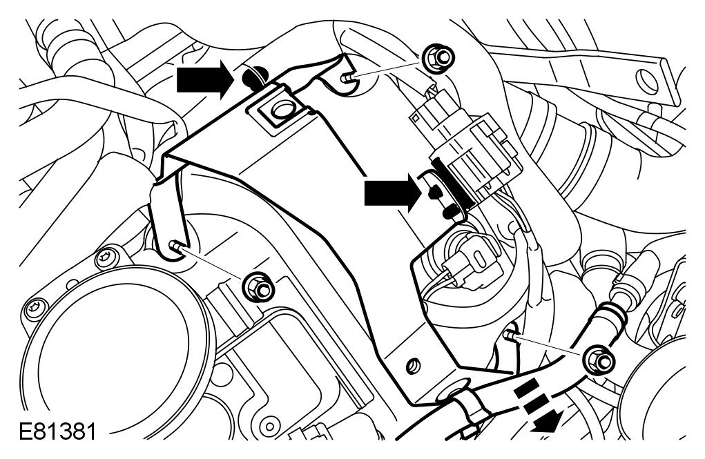
10 Remove the engine cover RH bracket.
- Remove the 3 nuts.
- Release the 2 wiring harness clips.
- Release the hose.
11 Disconnect the LH variable camshaft timing (VCT) oil control solenoid electrical connector.
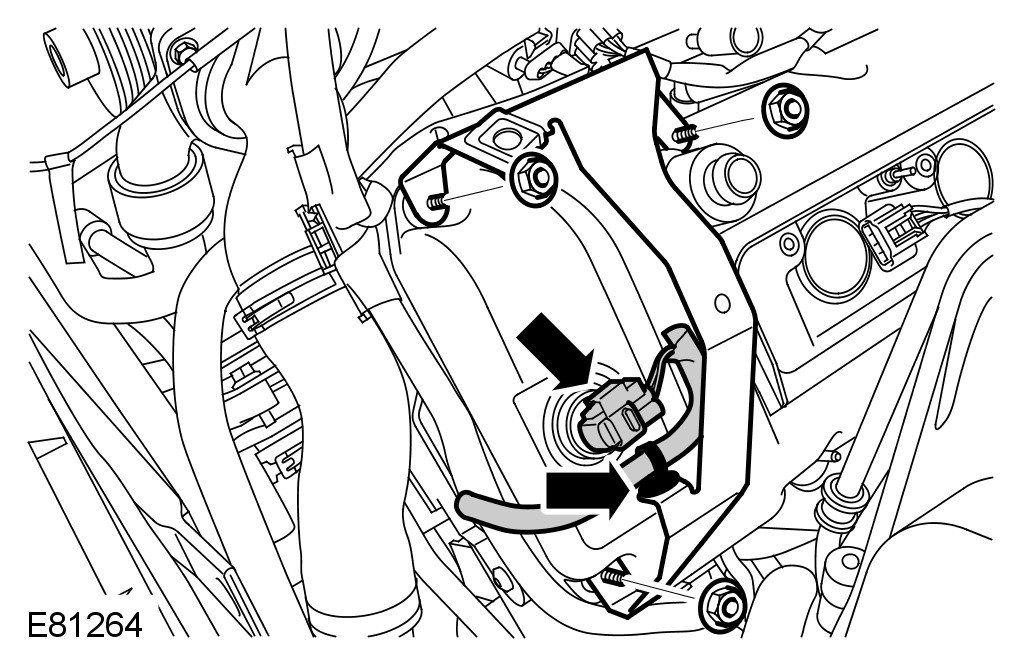
12 Remove the engine cover LH bracket.
- Remove the 3 nuts.
- Release the wiring harness.
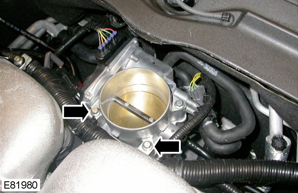
13 Release the wiring harness from the rear of the engine.
- Remove the 2 bolts.
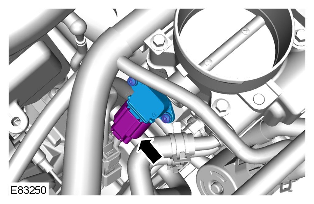
14 Disconnect the manifold absolute pressure (MAP) sensor electrical connector.
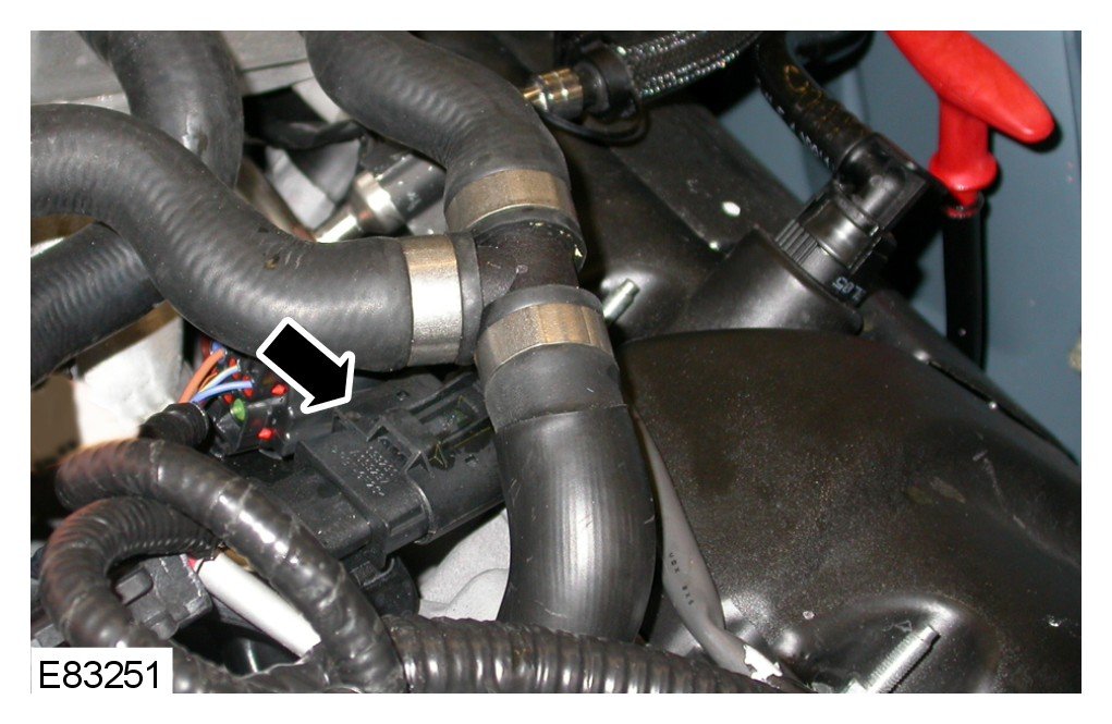
15 Disconnect the knock sensors (KS) electrical connector.
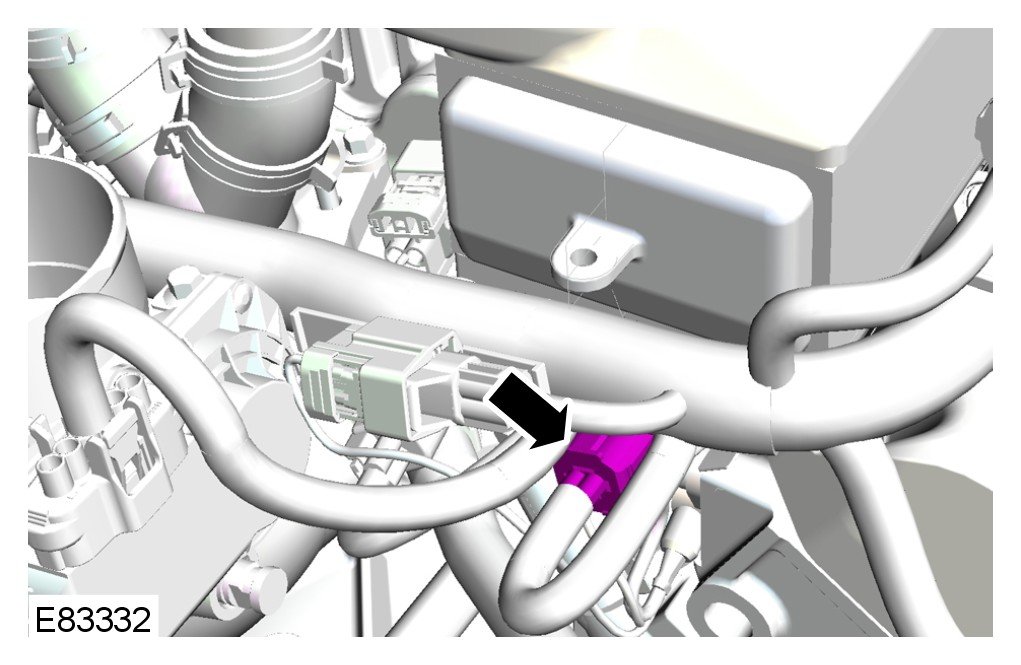
16 Disconnect the fuel temperature sensor electrical connector.
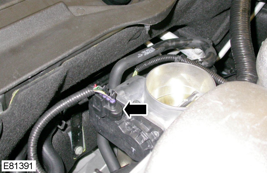
17 Disconnect the throttle position (TP) sensor electrical connector.
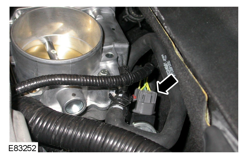
18 Disconnect the exhaust gas recirculation (EGR) valve electrical connector.
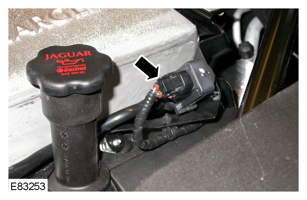
19 Disconnect the purge control valve (PCV) electrical connector.
- Release the wiring harness.
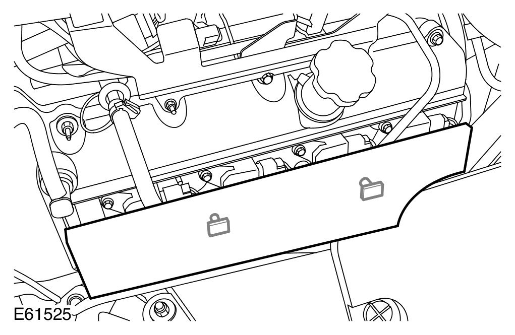
20
NOTE:
LH illustration shown, RH is similar.
Remove the ignition coil-on-plug cover.
- Release from the 2 clips.
- Repeat the above procedure for the RH side.
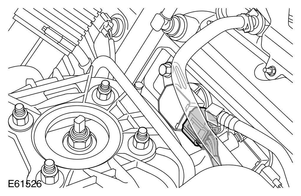
21
NOTE:
LH illustration shown, RH is similar.
Disconnect the ignition coil-on-plug electrical connector.
- Repeat the above procedure for the remaining 7 coil-on- plugs.
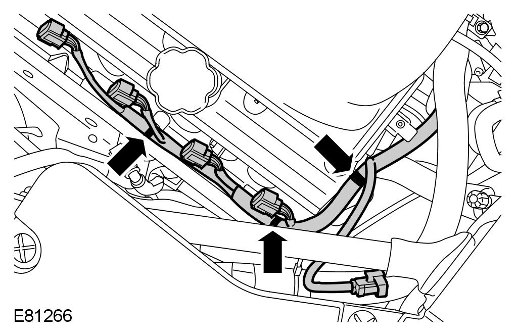
22
NOTE:
LH illustration shown, RH is similar.
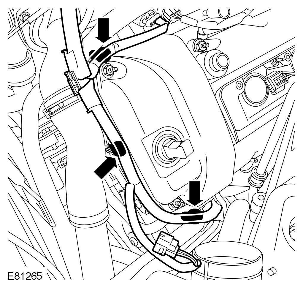
Release the coil-on-plug wiring harness.
- Release the 3 clips.
- Repeat the above procedure for the RH side.
23
NOTE:
LH illustration shown, RH is similar.
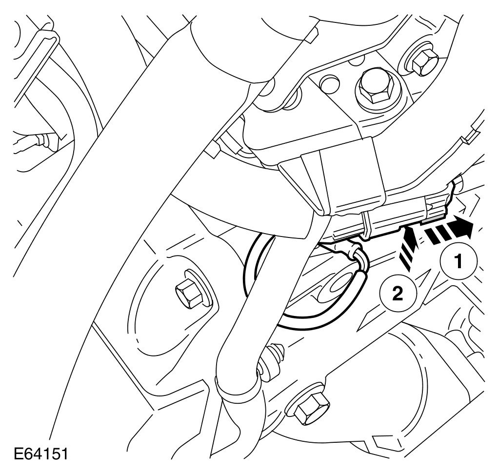
Release the engine wiring harness from the valve cover.
- Release the 3 clips.
- Repeat the above procedure for the RH side.
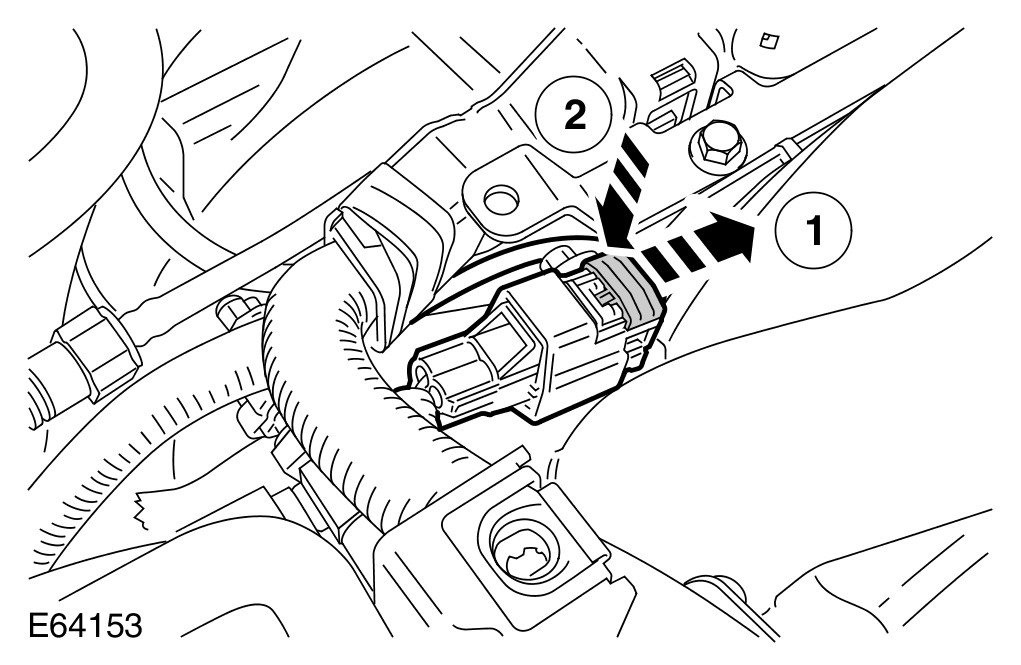
24 Disconnect the LH camshaft position CMP sensor electrical connector.
- Slide the red connector latch to one side.
25 Disconnect the RH CMP sensor electrical connector.
- Slide the red connector latch to one side.
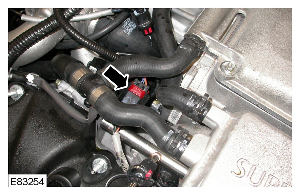
26 Disconnect the LH fuel injector wiring harness electrical connector.
- Slide the red connector latch to one side.
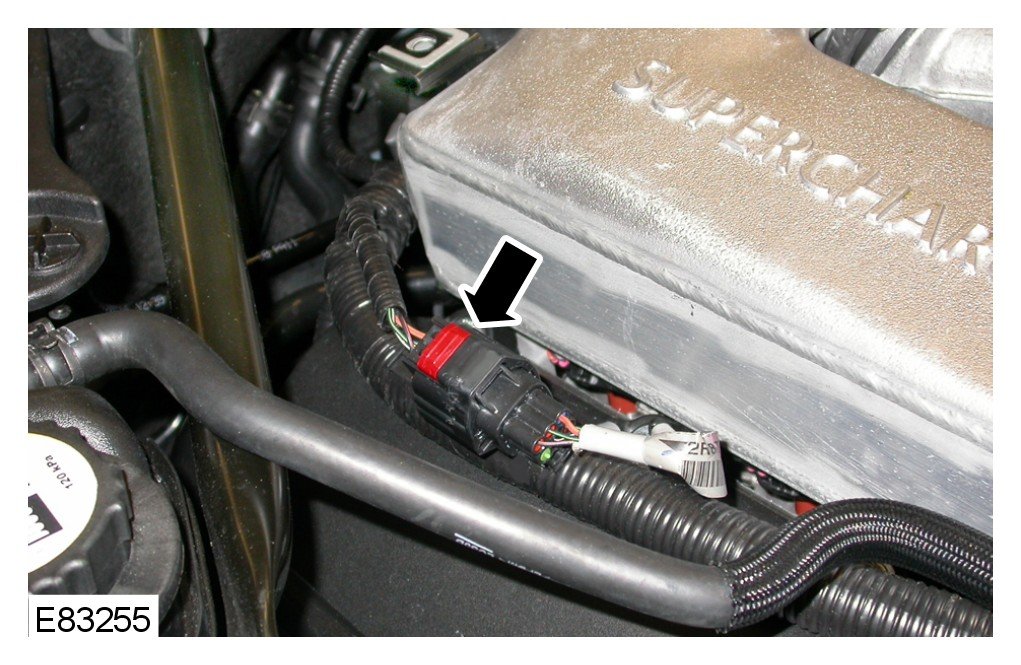
27 Disconnect the RH fuel injector wiring harness electrical connector.
- Slide the red connector latch to one side.
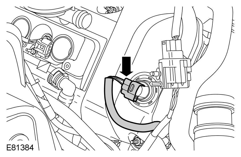
28 Disconnect the variable camshaft timing (VCT) oil control solenoid electrical connector.
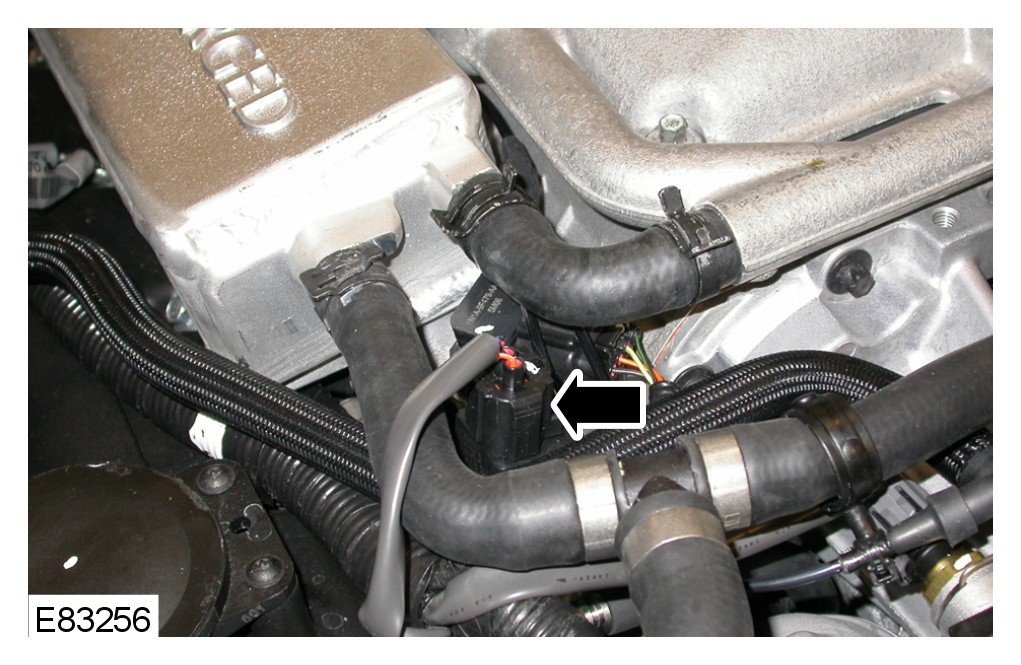
29 Disconnect the fuel rail pressure (FRP) sensor electrical connector.
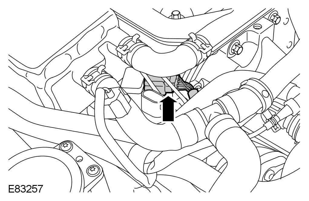
30 Disconnect the intake air temperature (IAT) sensor electrical connector.
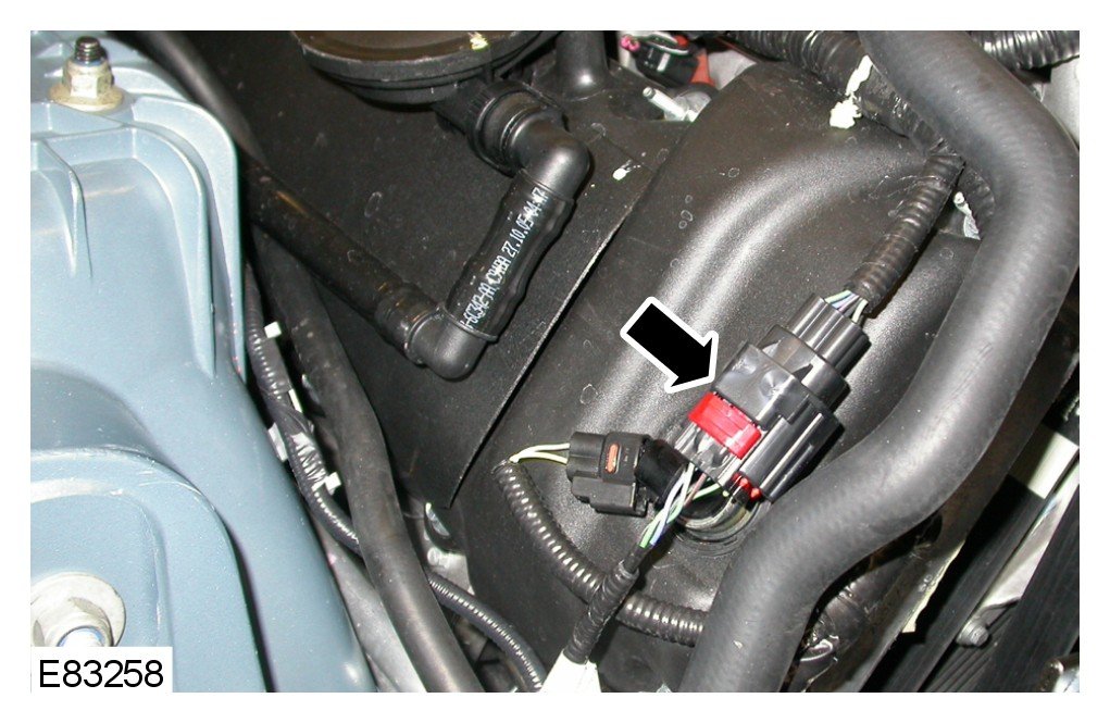
31 Disconnect the RH mass air flow (MAF) sensor electrical connector.
- Slide the red connector latch to one side.
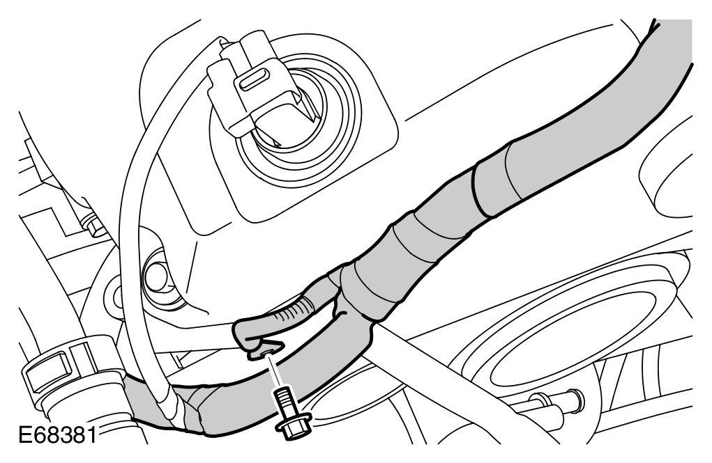
32 Disconnect the engine front cover ground cable.
- Remove the bolt.
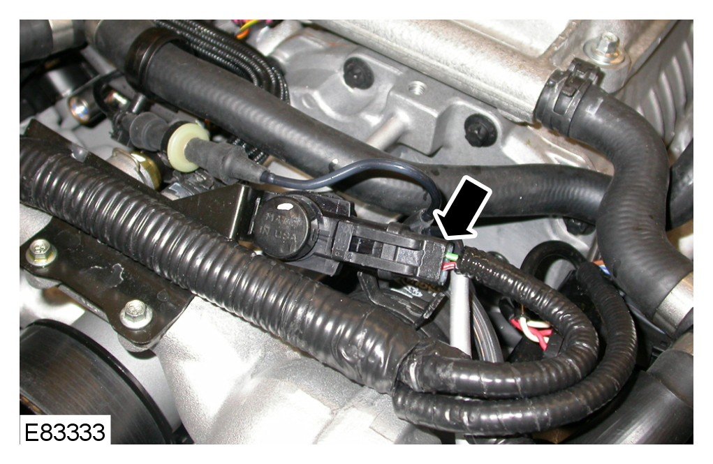
33 Disconnect the secondary air injection switching valve electrical connector.
34 Disconnect the engine coolant temperature (ECT) sensor electrical connector.
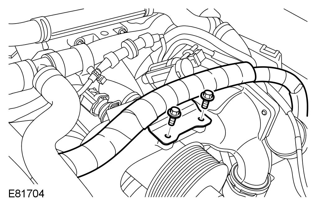
35 Release the engine wiring harness from the coolant manifold.
- Remove the 2 bolts.
36 Remove the power steering pump. For additional information, refer to Power Steering Pump - Vehicles With: Supercharger Service and Repair
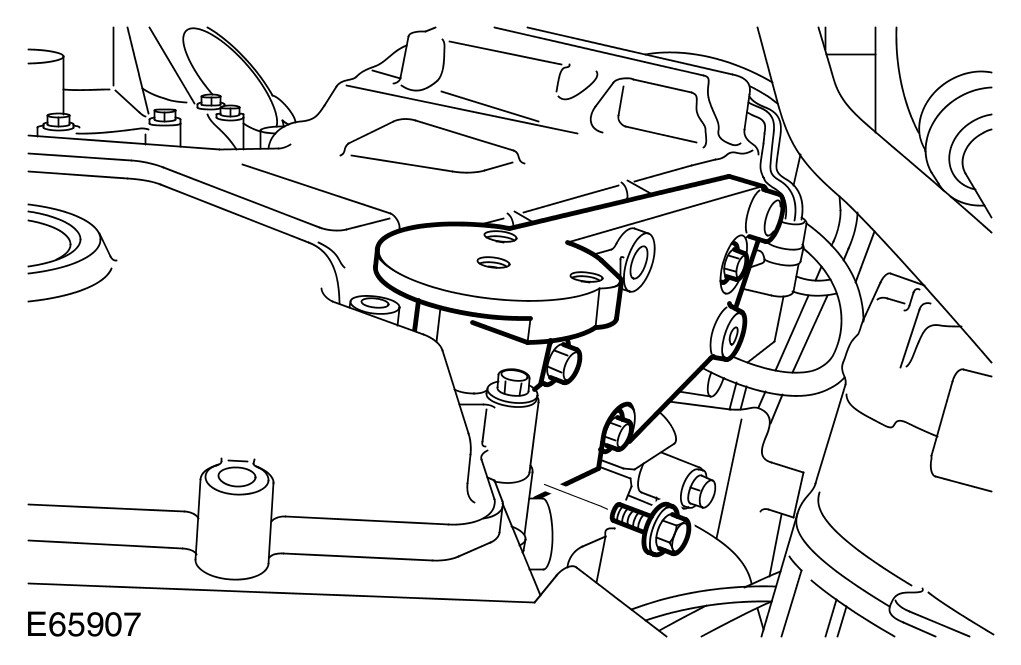
37 Remove the power steering pump mounting bracket.
- Remove the 4 bolts.
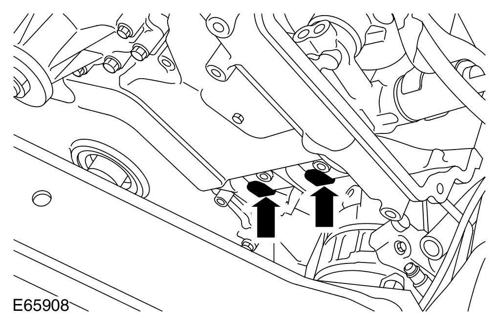
38 LH side: Release the engine wiring harness.
- Release the 2 clips.
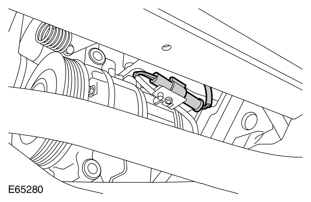
39 Disconnect the A/C compressor electrical connector.
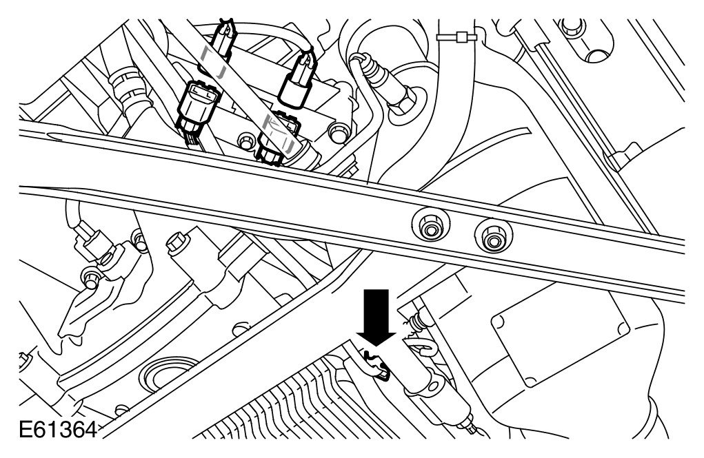
40 Release and disconnect the 2 LH HO2S electrical connectors.
- Release the clip.
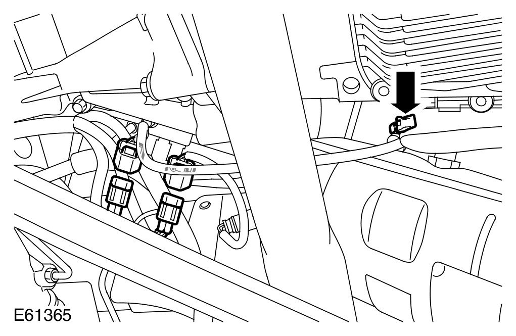
41 Release and disconnect the 2 RH HO2S electrical connectors.
- Release the clip.
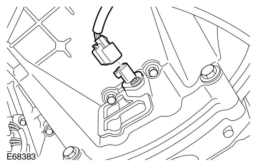
42
NOTE:
Clean the components general area prior to dismantling.
Disconnect the crankshaft position (CKP) sensor electrical connector.
43 Disconnect the starter motor battery positive and generator cables.
- Release the cover.
- Remove the nut.
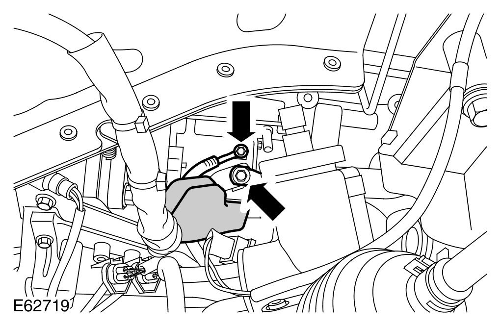
44 Disconnect the starter motor solenoid electrical connector.
- Remove and discard the nut.
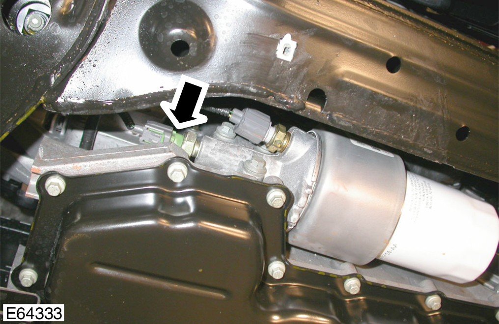
45 Disconnect the engine oil pressure (EOP) sensor electrical connector.
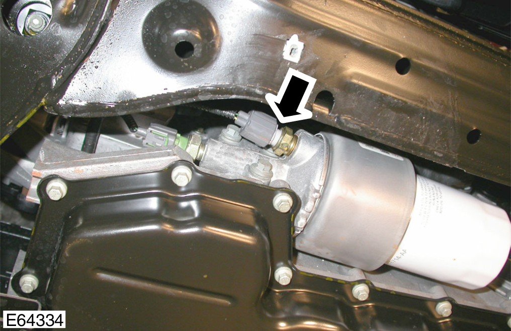
46 Disconnect the engine oil temperature sensor electrical connector.
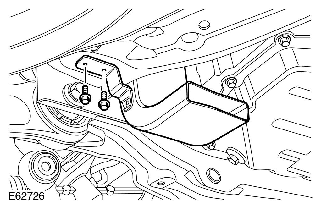
47 Remove the generator cooling duct.
- Remove the 2 screws.
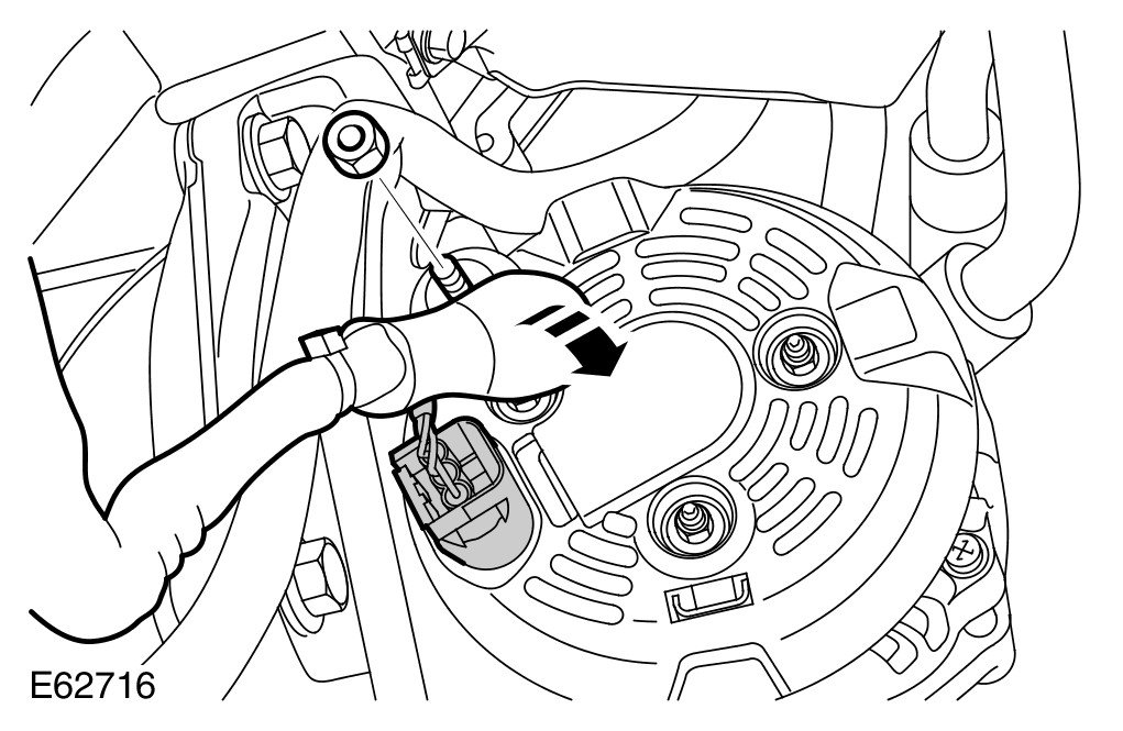
48 Disconnect the generator electrical connectors.
- Release the cover.
- Remove the nut.
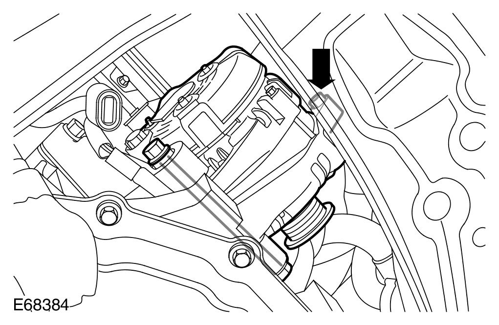
49 Release the generator.
- Remove the nut.
- Remove the nut and bolt.
- Position the generator aside to access the engine wiring harness clips.
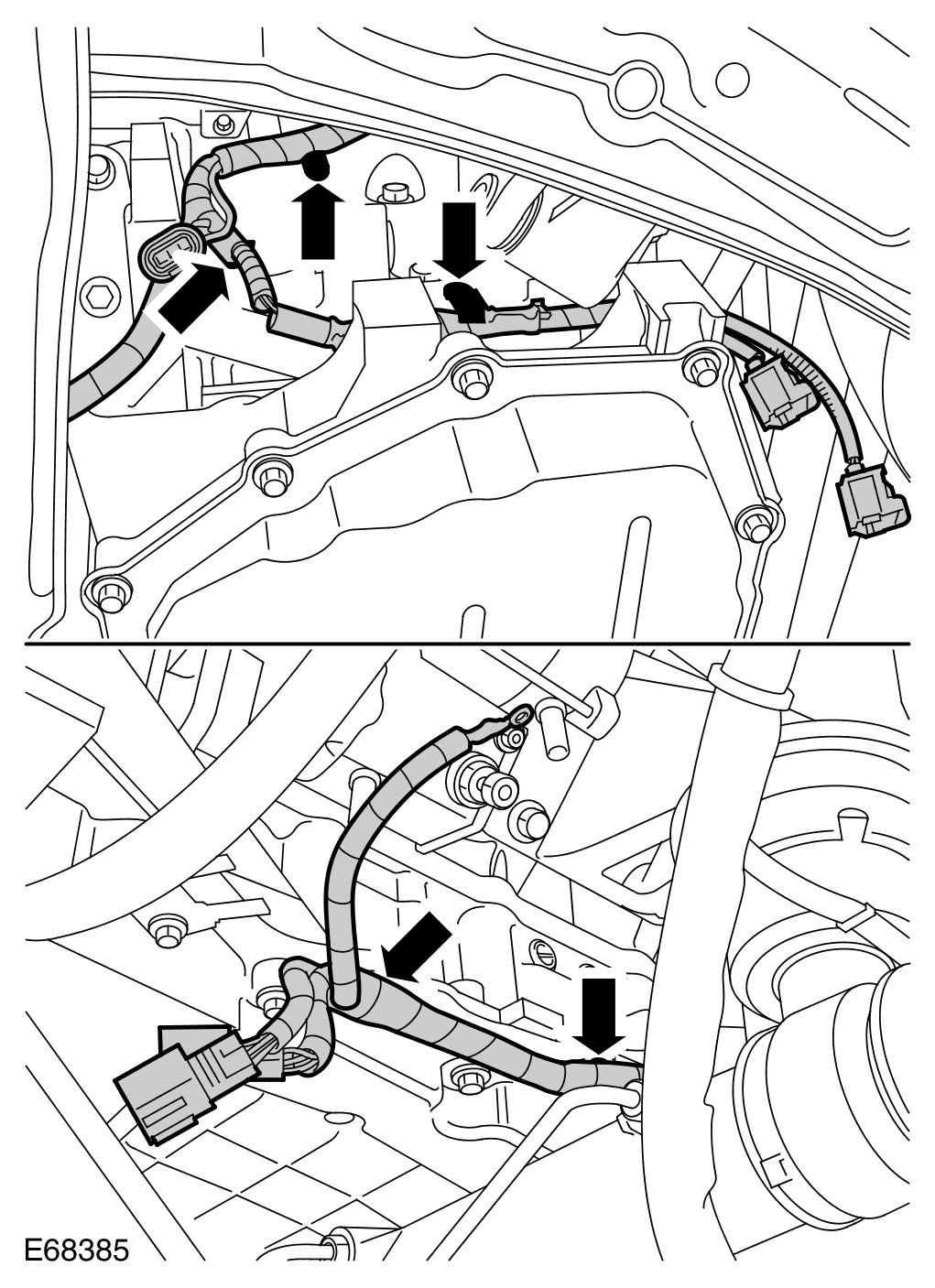
50 RH side: Release the engine wiring harness.
- Release the 5 clips.
51 Remove the engine wiring harness.
Installation
1 Install the engine wiring harness.
2 RH side: Attach the wiring harness.
- Secure the clips.
3 Install the generator.
- Tighten the nut to 25 Nm (18 lb.ft).
- Tighten the nut and bolt to 40 Nm (30 lb.ft).
4 Connect the generator electrical connectors.
- Tighten the nut to 12 Nm (9 lb.ft).
- Secure the cover.
5 Install the generator cooling duct.
- Tighten the screws.
6 Connect the engine oil temperature sensor electrical connector.
7 Connect the EOP sensor electrical connector.
8 Connect the starter motor solenoid electrical connector.
- Tighten the new nut to 7 Nm (5 lb.ft).
9 Connect the starter motor battery positive and generator cables.
- Tighten the nut to 10 Nm (7 lb.ft).
- Secure the cover.
10 Connect the CKP sensor electrical connector.
11 Connect and secure the HO2S electrical connectors.
- Secure the 2 clips.
12 Connect the A/C compressor electrical connector.
13 LH side: Attach the wiring harness.
- Secure the clips.
14 Install the power steering pump mounting bracket.
- Tighten the bolts to 25 Nm (18 lb.ft).
15 Install the power steering pump. For additional information, refer to Power Steering Pump - Vehicles With: Supercharger Service and Repair
16 Attach the engine wiring harness to the coolant manifold.
- Tighten the bolts to 6 Nm (4 lb.ft).
17 Connect and secure the ECT sensor electrical connector.
18 Connect the secondary air injection switching valve electrical connector.
19 Connect the engine front cover ground cable.
- Tighten the bolt to 10 Nm (7 lb.ft).
20 Connect the MAF sensor electrical connector.
21 Connect the IAT sensor electrical connector.
22 Connect the FRP sensor electrical connector.
23 Connect and secure the fuel injector wiring harness electrical connectors.
24 Connect and secure the CMP sensor electrical connectors.
25 Connect the ignition coil-on-plug electrical connectors.
26 Attach the coil-on-plug wiring harness.
- Secure with the clips.
27 Attach the engine wiring harness to the valve covers.
- Secure with the clips.
28 Connect the PCV electrical connector.
- Secure the wiring harness.
29 Install the ignition coil-on-plug covers.
- Position and secure the clips.
30 Connect the VCT solenoid electrical connectors.
31 Connect the EGR valve electrical connector.
32 Connect the TP sensor electrical connector.
33 Connect the fuel temperature sensor electrical connector.
34 Connect the KS electrical connector.
35 Connect the FRP sensor electrical connector.
36 Connect the MAP sensor electrical connector.
37 Attach the engine wiring harness to the rear of the engine.
- Tighten the bolts to 10 Nm (7 lb.ft).
38 Install the engine cover LH bracket.
- Tighten the nuts to 6 Nm (4 lb.ft).
- Attach the wiring harness.
39 Install the engine cover RH bracket.
- Tighten the nuts to 6 Nm (4 lb.ft).
- Secure the wiring harness.
- Secure the hose.
40 Attach the ground cable to the power distribution box bracket.
- Tighten the nuts to 25 Nm (18 lb.ft).
41 Attach the engine wiring harness to the engine compartment side wall.
- Position and secure the grommet.
42 Connect the engine wiring harness electrical connector and secure with the captive bolt.
43 Recharge the A/C system.
44 Install the fan cowl.
- Secure with the clips.
45 Install the ECM. For additional information, refer to Engine Control Module (ECM) Service and Repair
46 Install the intake air resonator. For additional information, refer to Intake Air Resonator Service and Repair
47 Connect the battery ground cable and install the cover. For additional information, refer to Specifications [1][2]Battery