Electronic Engine Controls 1
Electronic Engine Controls
COMPONENT LOCATION SHEET 1 of 2
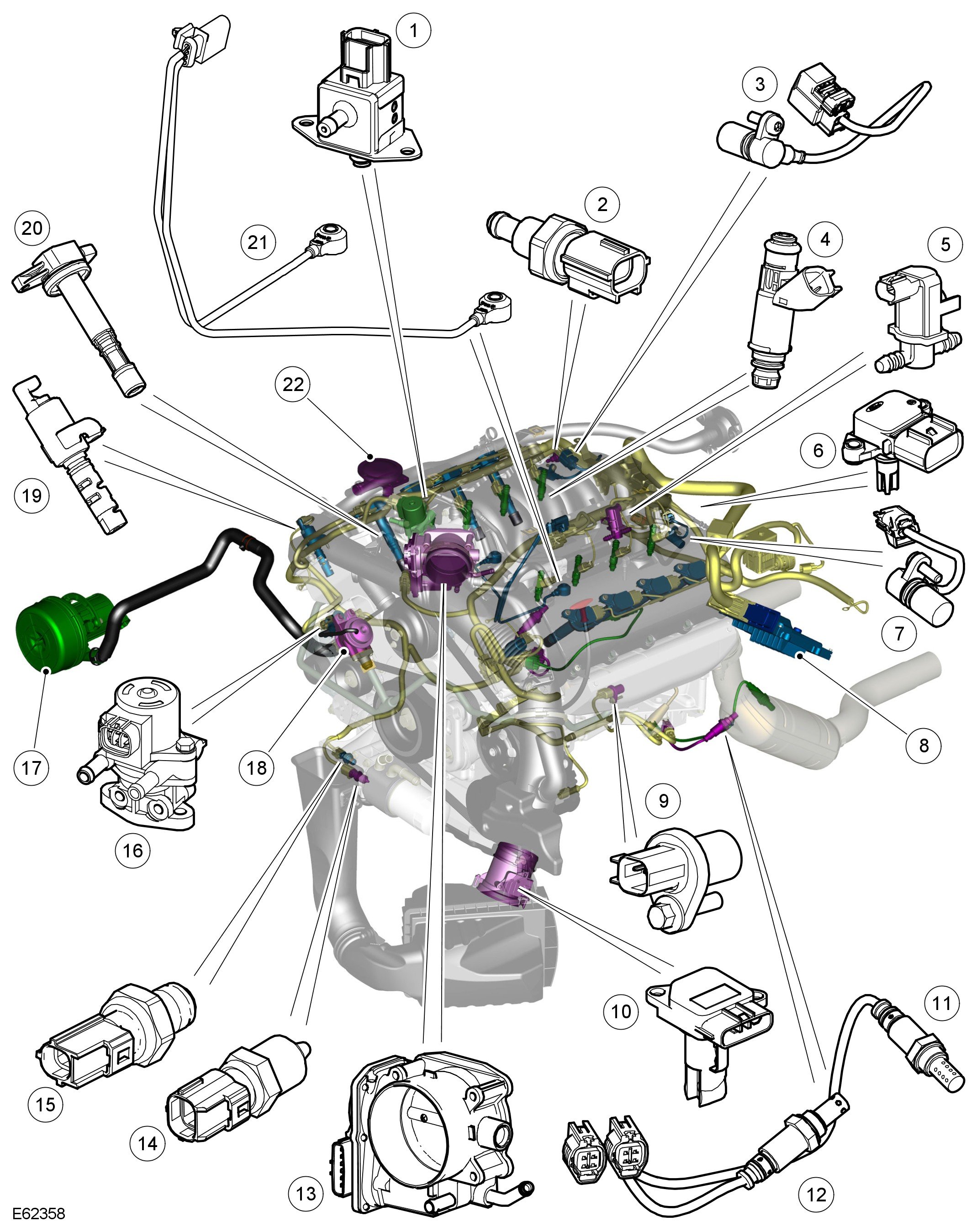
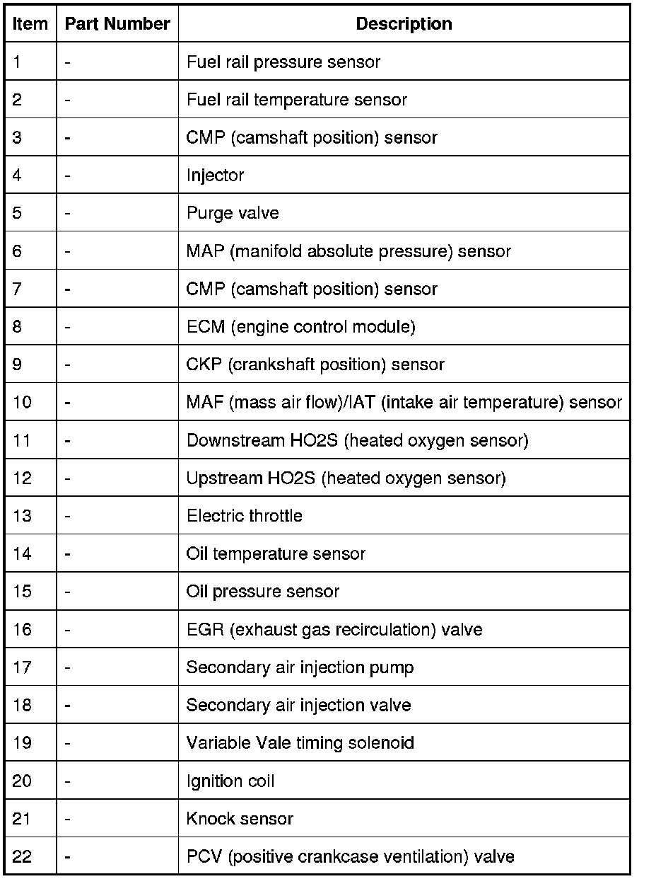
COMPONENT LOCATION SHEET 2 of 2
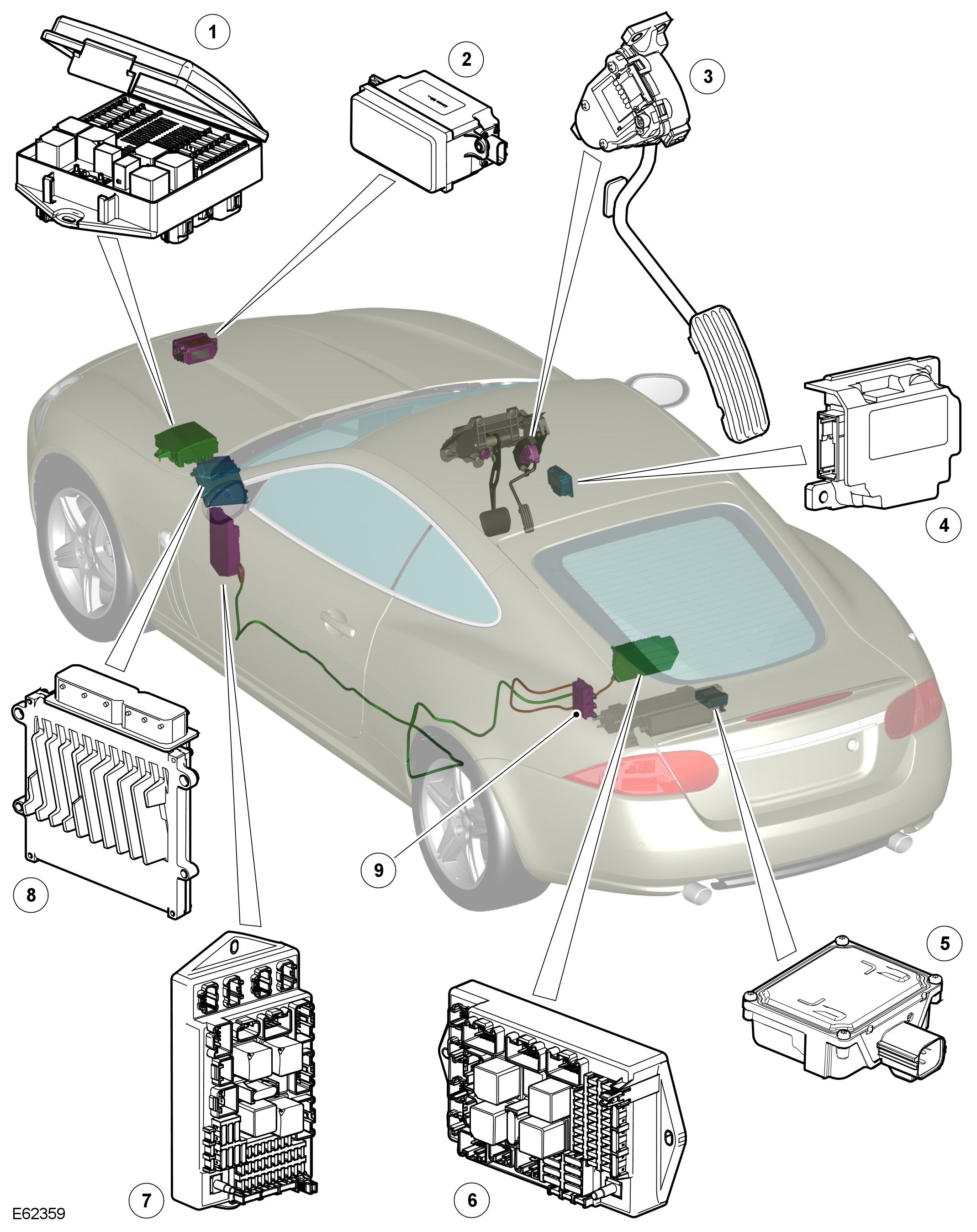
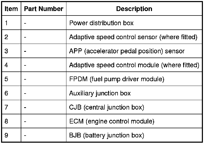
INTRODUCTION
The V8 4.2 Liter naturally aspirated engine is controlled by an ECM (engine control module) manufactured by DENSO. The Engine Management System (EMS) controls the following:
- Engine fueling
- Ignition timing
- Closed loop fueling
- Knock control
- Idle speed control
- Emission control
- On Board Diagnostic
- Interface with the immobilization system
- Speed control
The ECM (engine control module) controls the engine fueling by providing sequential fuel injection to all cylinders. Ignition is controlled by a direct ignition system, provided by eight plug top coils. The ECM (engine control module) is able to detect and correct for ignition knock on each cylinder and adjust the ignition timing for each cylinder to achieve optimum performance.
The ECM (engine control module) uses a torque-based strategy to generate the torque required by the driver and other vehicle control modules. The EMS uses various sensors to determine the torque required from the engine. The EMS also interfaces with other vehicle electronic control modules's, via the CAN (controller area network) bus, to obtain additional information (e.g. road speed from the ABS (anti-lock brake system) control module). The EMS processes these signals and decides how much torque to generate. Torque is then generated by using various actuators to supply air, fuel and spark to the engine (electronic throttle, injectors, coils, etc.).
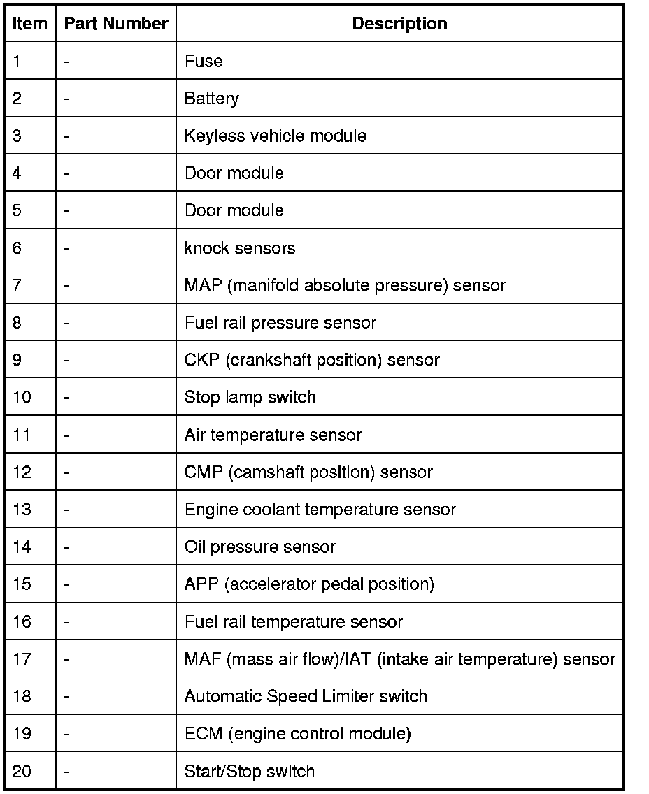
The EMS comprises the following inputs:
- CMP (camshaft position) sensor
- CKP (crankshaft position) sensor
- Fuel rail pressure sensor
- MAF (mass air flow) sensor
- Knock sensors
- Fuel rail temperature sensor
- ECT (engine coolant temperature) sensor
- Engine oil temperature sensor
- MAP (manifold absolute pressure) sensor
- Electric throttle feedback sensor
- Secondary Air Injection (SAI) MAP (manifold absolute pressure) sensor
- APP (accelerator pedal position) sensor
- DMTL (NAS only)
- Cooling fan speed feedback.
- Heated Exhaust Gas Oxygen (HEGO) sensors
- Universal Heated Exhaust Gas Oxygen (UHEGO) sensors
- Brake switch
- Speed control cancel/suspend switch
- Automatic speed limiter switch
- Crank request signal
- IAT (intake air temperature) sensor
- External air temperature sensor
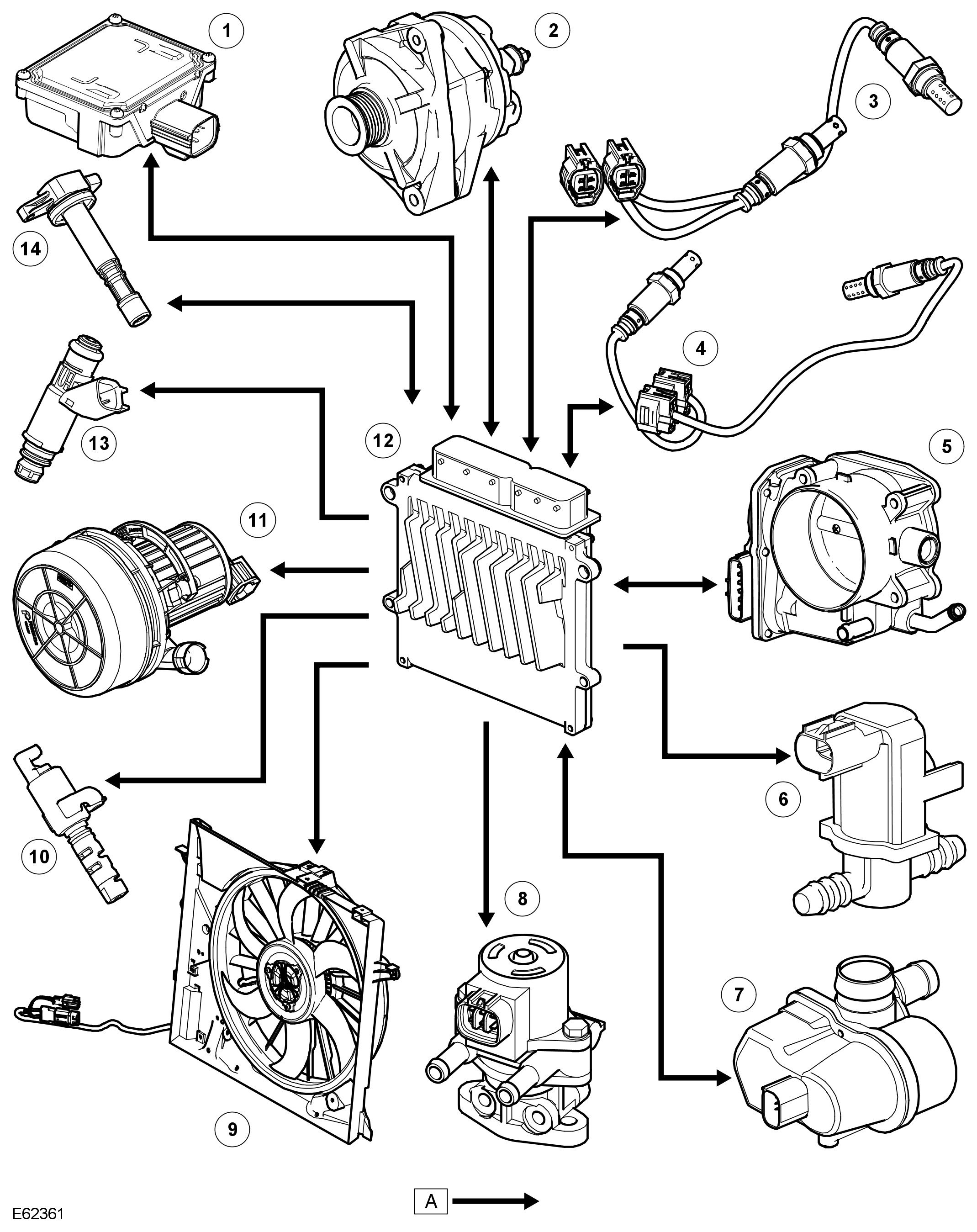
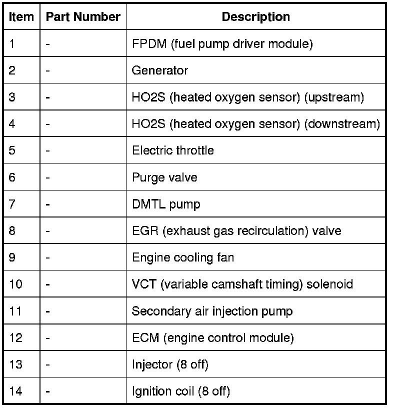
The EMS comprises the following outputs:
- Fuel injectors
- Ignition coils
- Engine cooling fan
- Electric throttle
- Electric fuel pump driver module
- VCT (variable camshaft timing) solenoids
- Purge valve
- EGR (exhaust gas recirculation) valve
- Secondary air injection pump
- Starter relay control
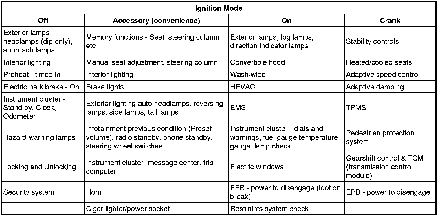
IGNITION MODES
The vehicle has a possible 4 ignition modes. The modes and systems that are active in each mode are detailed in the following table.
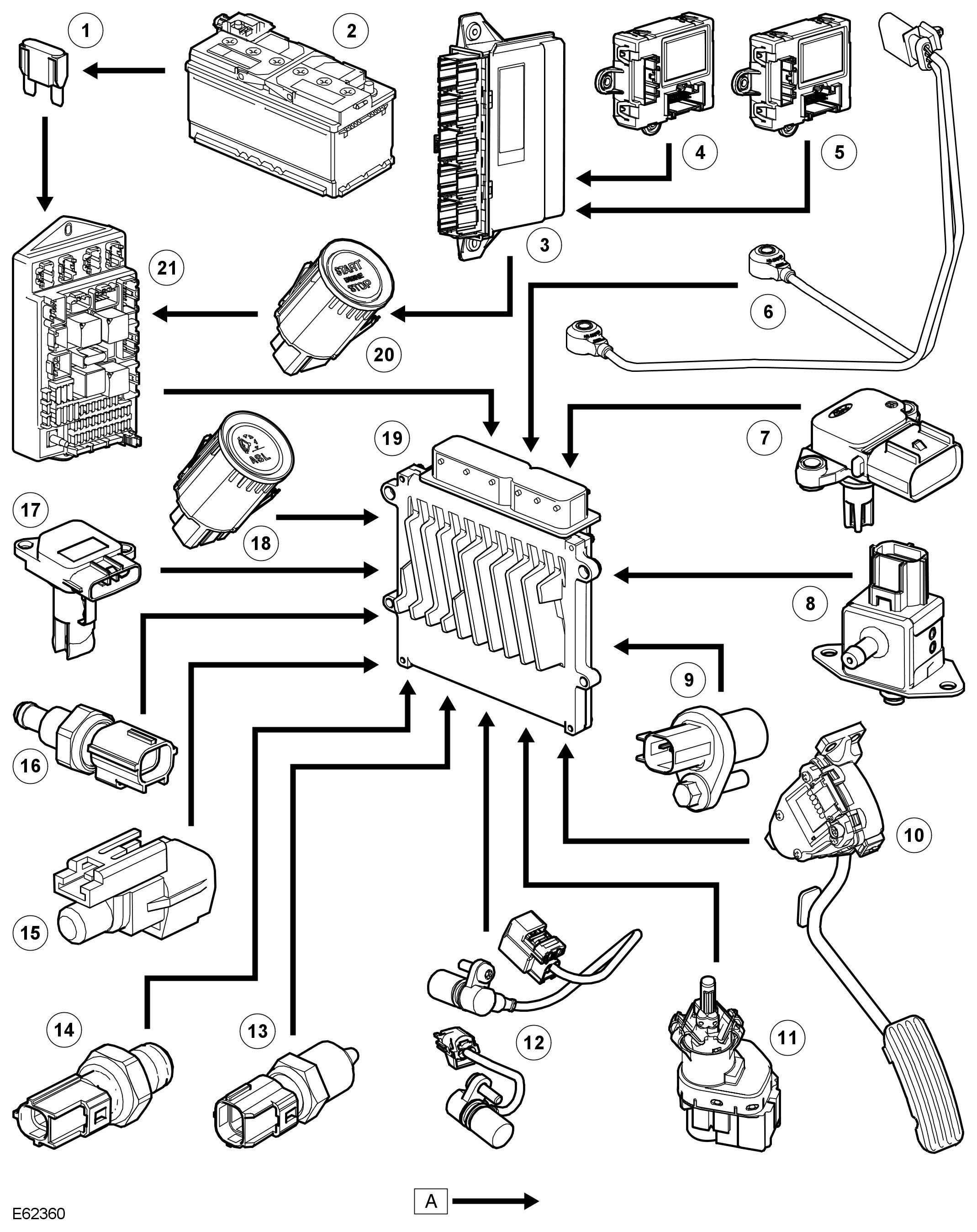
CONTROL DIAGRAM SHEET 1 of 3
NOTE:
A = Hardwired connection
CONTROL DIAGRAM SHEET 2 of 3
NOTE:
A = Hardwired connection
CONTROL DIAGRAM SHEET 3 of 3
NOTE:
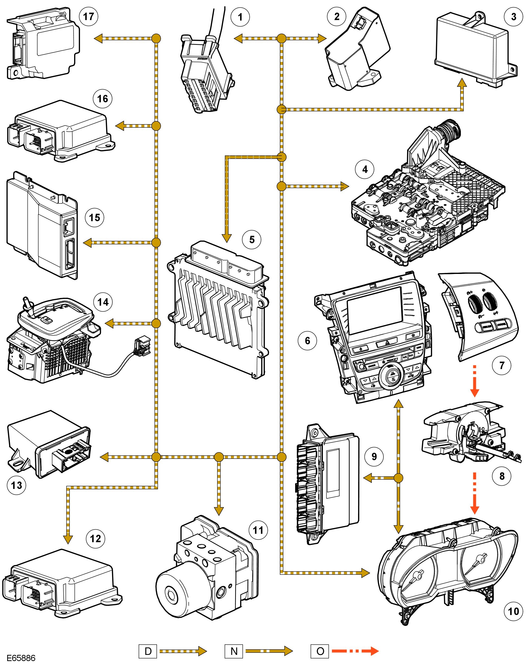
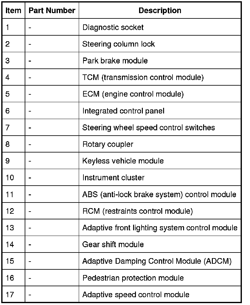
D = High speed CAN (controller area network) bus; N=Medium speed CAN (controller area network) bus; O = LIN (local interconnect network) bus