Part 1
TRANSFER CASE OVERHAUL - Part 1Parking Brake Removal
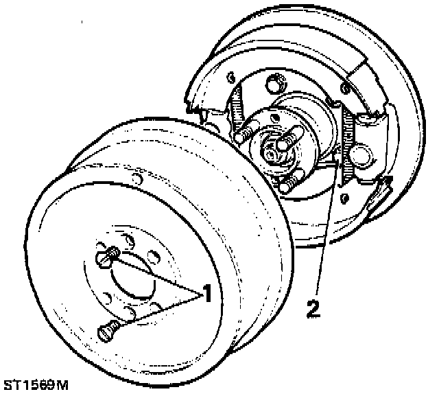
1. Remove two countersunk screws and withdraw brake drum.
2. Remove four bolts securing the brake back-plate; the two bottom fixings retain the oil catcher.
NOTE: A hexagonal type socket should be used for these bolts.
Bottom Cover Removal
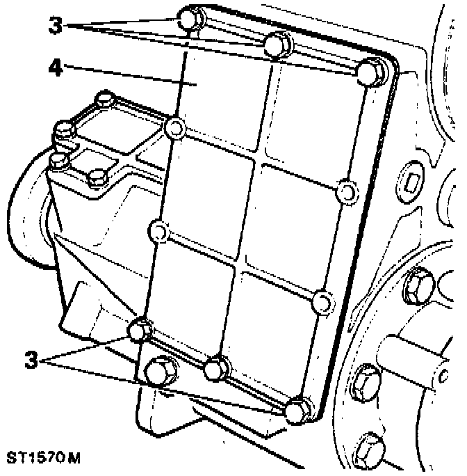
3. Remove the six bolts and washers retaining the bottom cover.
4. Remove the bottom cover and gasket, discard the gasket.
Intermediate Shaft And Gear Cluster Removal
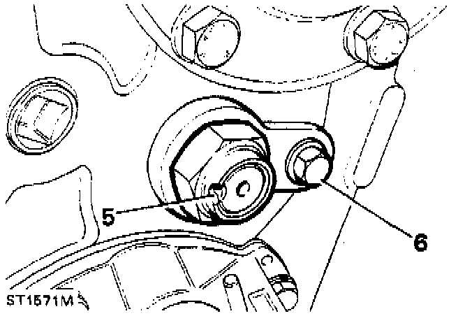
5. Release stake nut from recess in intermediate shaft, remove stake nut and discard.
6. Unscrew the single bolt and remove anti-rotation plate at the rear face of the transfer box.
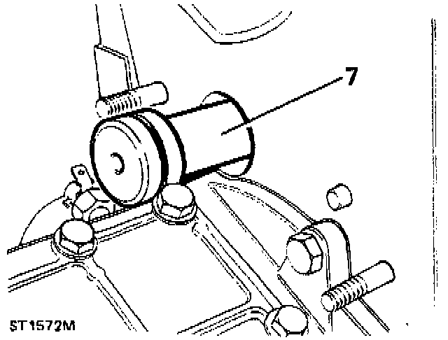
7. Tap the intermediate gear shaft from the transfer box.
8. Lift out the intermediate gear cluster and bearing assembly.
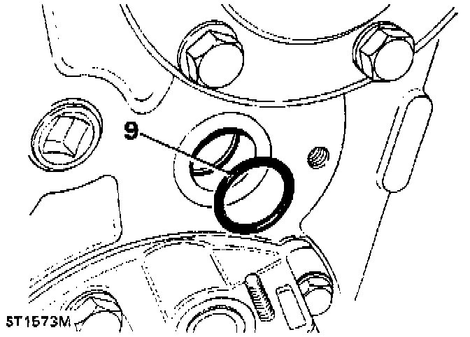
9. Remove the O-rings from the intermediate gear shaft and from inside the transfer box and discard.
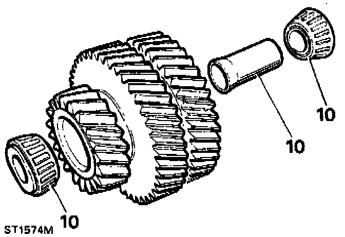
10. Remove the taper roller bearings and bearing spacer from the intermediate gear cluster assembly.
Power Take-Off Cover Removal
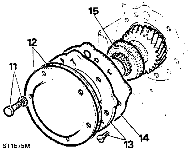
11. Remove five bolts and washers retaining the take-off cover.
12. Remove the cover and gasket, discard the gasket.
Input Gear Removal
13. Remove the two countersunk screws and detach the main shaft bearing housing.
14. Remove the gasket and discard.
15. Withdraw the input gear assembly.
16. Pry out and discard the oil seal at the front of the transfer box casing using service tool 18G1271.
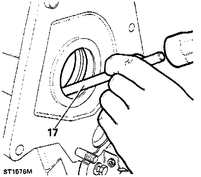
17. Drive out the input gear front bearing track.
High/Low Cross-Shaft Housing Removal
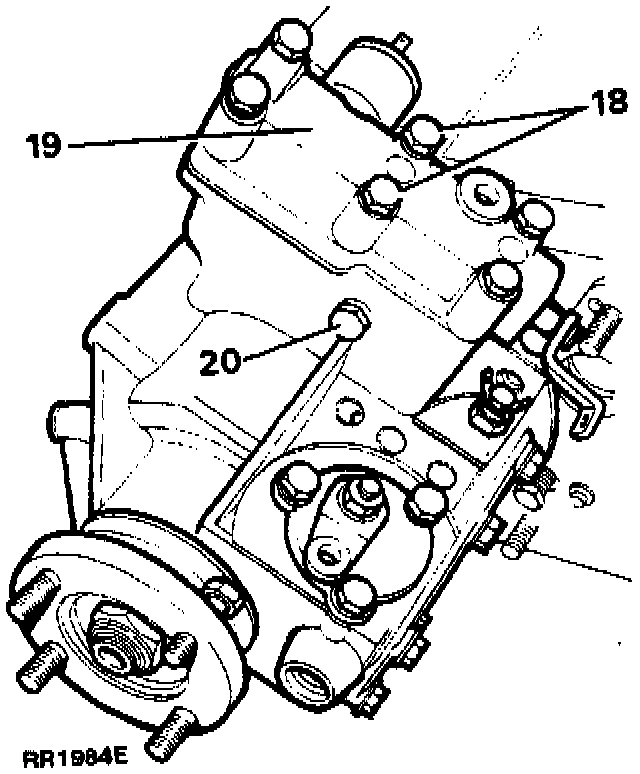
18. Remove the six bolts and washers retaining the cross-shaft housing, ground lead and retaining clip.
19. Remove the cross-shaft housing and gasket, discard the gasket.
Front Output Housing Removal
20. Remove the eight bolts and washers and detach the output housing from the transfer box casing, taking care not to mislay the dowel. Remove the gasket and discard.
Centre Differential Removal
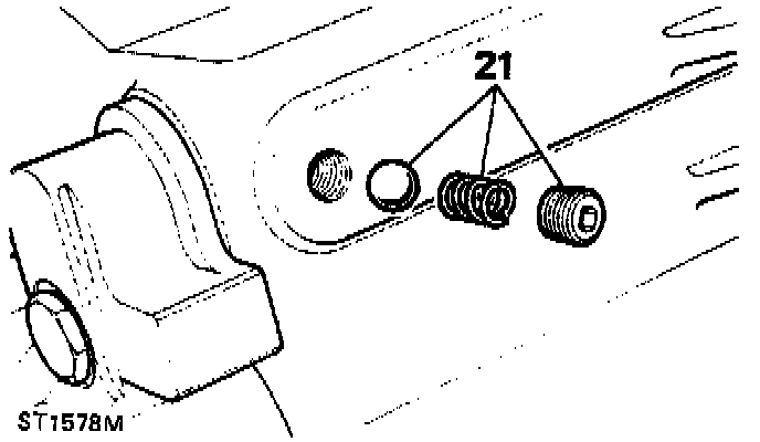
21. Remove high/low selector shaft detent plug, spring and retrieve the ball with a suitable magnet.
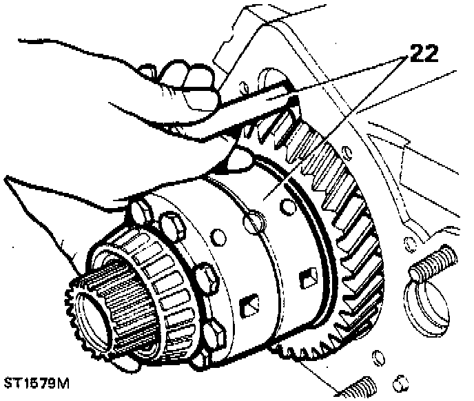
22. Withdraw the center differential and selector shaft/fork assembly.
Rear Output Housing Removal
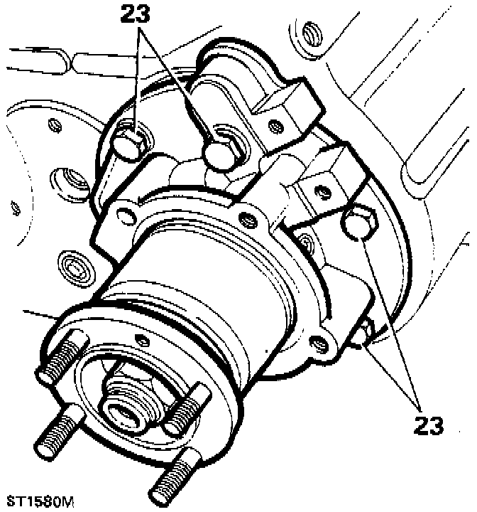
23. Remove six bolts and washers and detach the rear output housing and shaft assembly from the transfer casing.
24. Remove the gasket and discard.
Transfer Case Overhaul - Dismantling
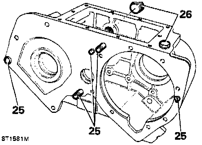
25. Inspect the studs and dowels for wear or damage. Remove if replacements are required.
26. Remove the magnetic drain plug, copper washer and filler/level plug. Discard the washer.
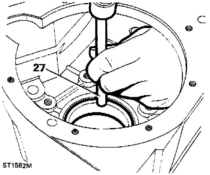
27. Drive out differential rear bearing track.
28. Clean all areas of the transfer casing ensuring all traces of Loctite(r) are removed from faces and threads.
Transfer Case Overhaul - Re-Assembling
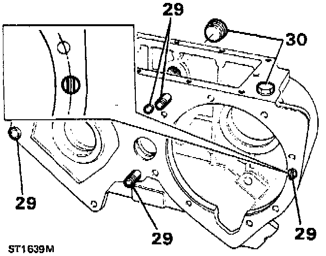
29. If previously removed, fit studs and dowels to front face of the transfer casing. Use new components where necessary.
NOTE: The position of the radial dowel blade is set in line with the circle which is formed by the front output housing fixing holes.
30. Refit magnetic drain plug with new copper washer and tighten to 25-35 Nm (19-26 ft lb), loosely fit the filler/level plug.
Rear Output Housing Overhaul-Dismantling
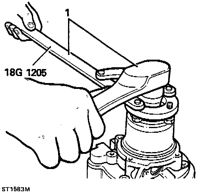
1. Using flange wrench 18G1205 and socket wrench remove the flange nut, steel and felt washers. Ensure flange bolts are fully engaged in the wrench.
2. Remove output flange with circlip attached. If necessary, use a two-legged puller.
NOTE: The circlip need only be released if the flange bolts are to be replaced.
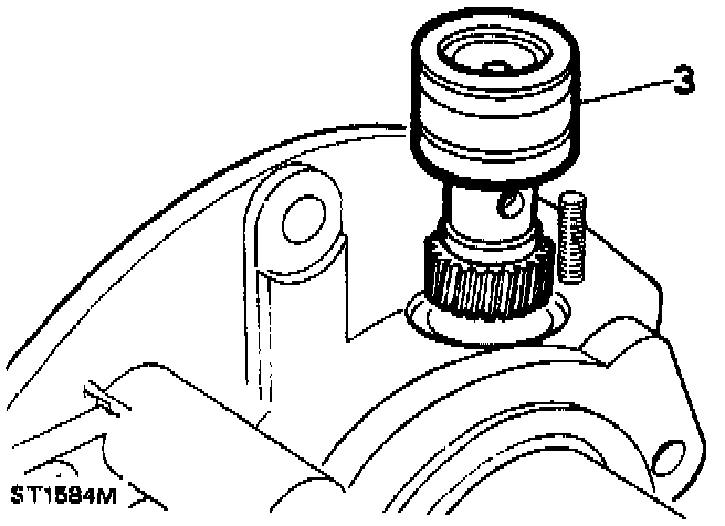
3. Remove speedo-drive housing. This can be eased out with a screwdriver.
4. Remove housing from the vice and drive out the output shaft, by striking the flange end of the shaft.
5. Carefully pry off the oil catch ring using a screwdriver in the slot provided.
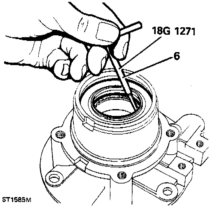
6. Pry out and discard the seal from the output housing using tool 18G1271.
7. Using circlip pliers 18G257, remove the circlip retaining the bearing.
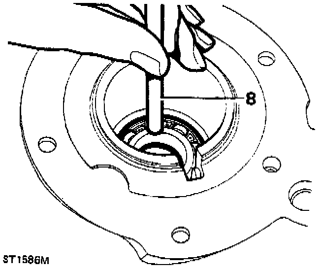
8. Drive out the bearing from the rear of the housing.
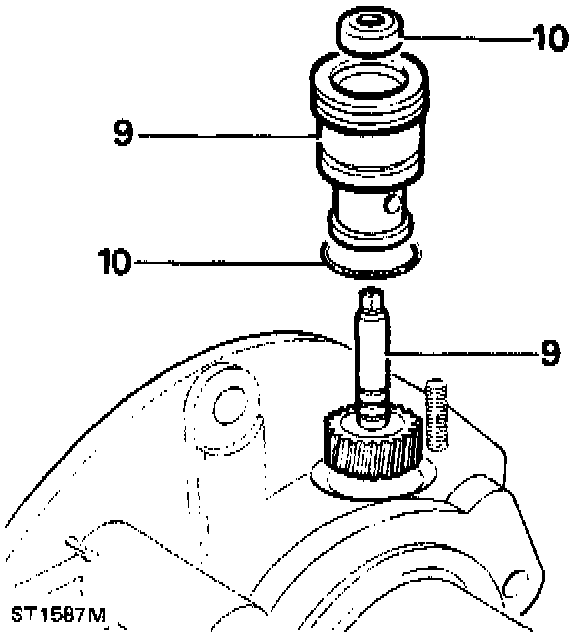
9. Remove speedometer gear (driven) from its housing.
10. Remove the O-ring and oil seal and discard.
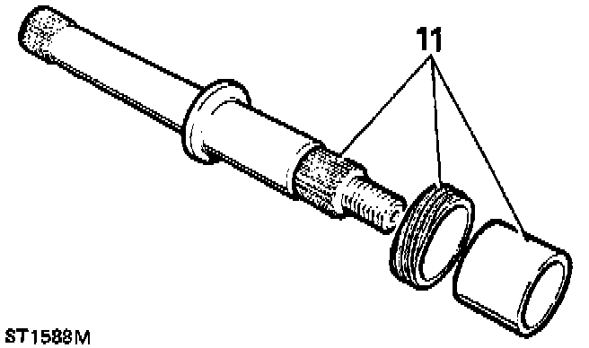
11. Slide off spacer and speedometer drive gear from output shaft.
12. Clean all parts, replace the O-ring, oil seals, felt seal and flange nut. Examine all other parts for wear or damage and replace, if necessary.
Re-Assembling
13. Press output bearing into the housing. Do not use excessive force. To facilitate fitting the bearing, heat the output housing case. This is not to exceed 100°C (212°F).
14. Retain bearing with circlip, using circlip pliers 18G257.
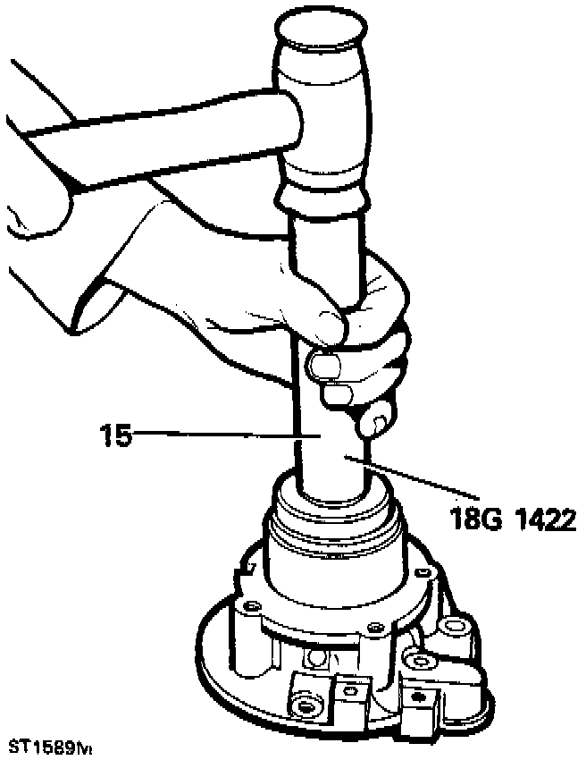
15. Pre-grease between the seal lips and fit new seal (open side inwards) using tool 18G1422. The seal should just make contact with the bearing circlip.
16. Carefully coat the lips of the seal with clean grease and refit oil catch ring onto output housing.
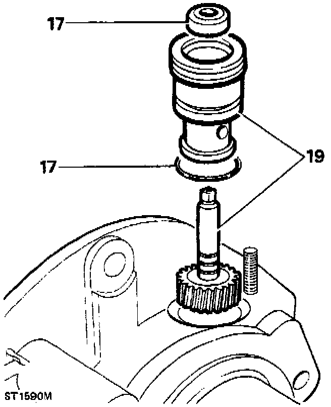
17. Fit the O-ring and oil seal (open side inwards) to speedometer housing.
18. Lubricate the O-ring and seal with oil.
19. Locate speedometer gear (driven) in housing and press into position.
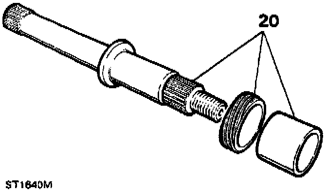
20. Slide drive gear and spacer on to the output shaft.
21. Locate output shaft into the bearing in the housing and drive into position.
22. Locate speedometer gear (driven) housing assembly into the output housing and press in until flush with the housing face.
Centre Differential Unit Overhaul-Dismantling
1. Secure center differential unit to a vice fitted with soft jaws, and release stake nut from recess.
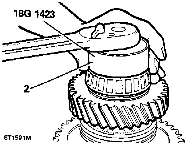
2. Remove stake nut using tool 18G9423 and suitable socket wrench and discard stake nut.
3. Remove the differential unit from the vice.
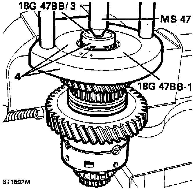
4. Secure hand press MS47 in vice with collars 18G47BB-1 and using button 18G47BB/3 remove the rear taper bearing and collars.
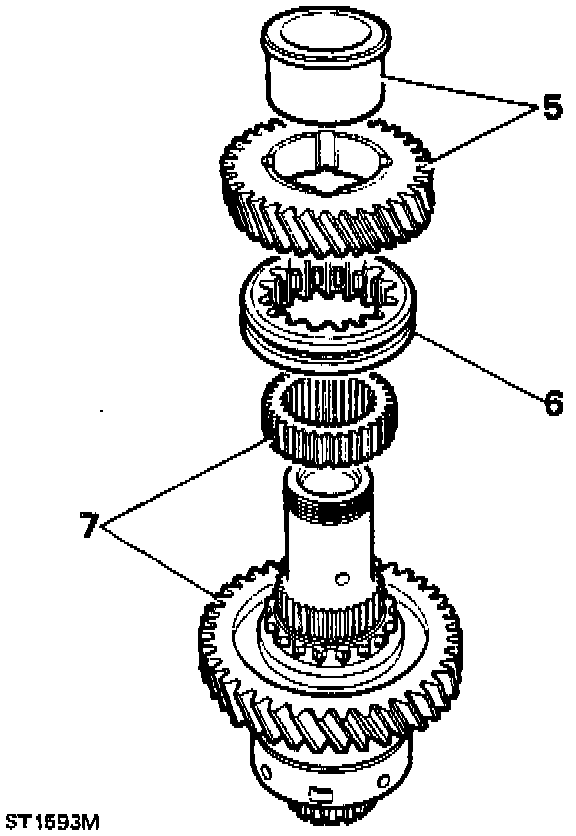
5. Remove the high range gear and bush, taking care not to disturb the high/low sleeve.
6. Mark the relationship of the high/low sleeve to the hub and then remove the sleeve.
7. Using a suitable press behind the low range gear carefully remove the high/low hub and low range gear.
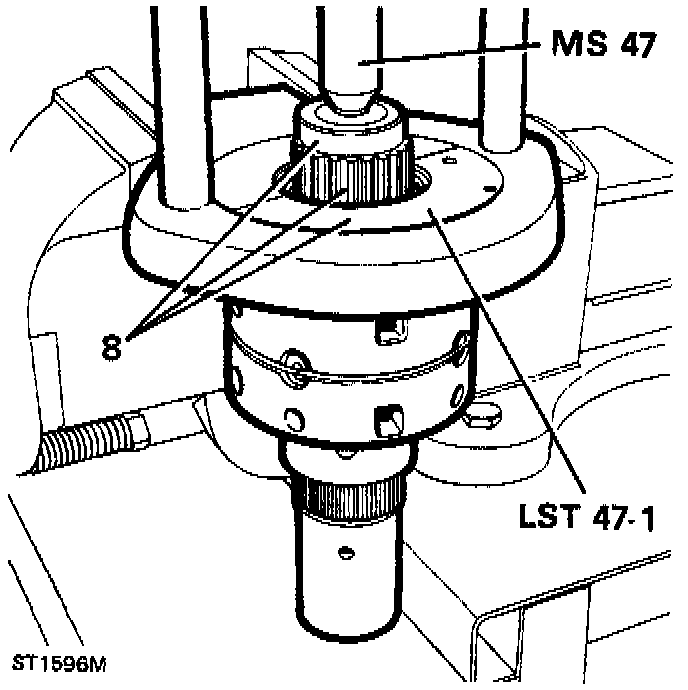
8. Substituting collar LST47-1 remove front taper roller bearing.
9. Remove hand press from the vice.
10. Using soft jaws secure the differential unit in the vice by gripping the hub splines.
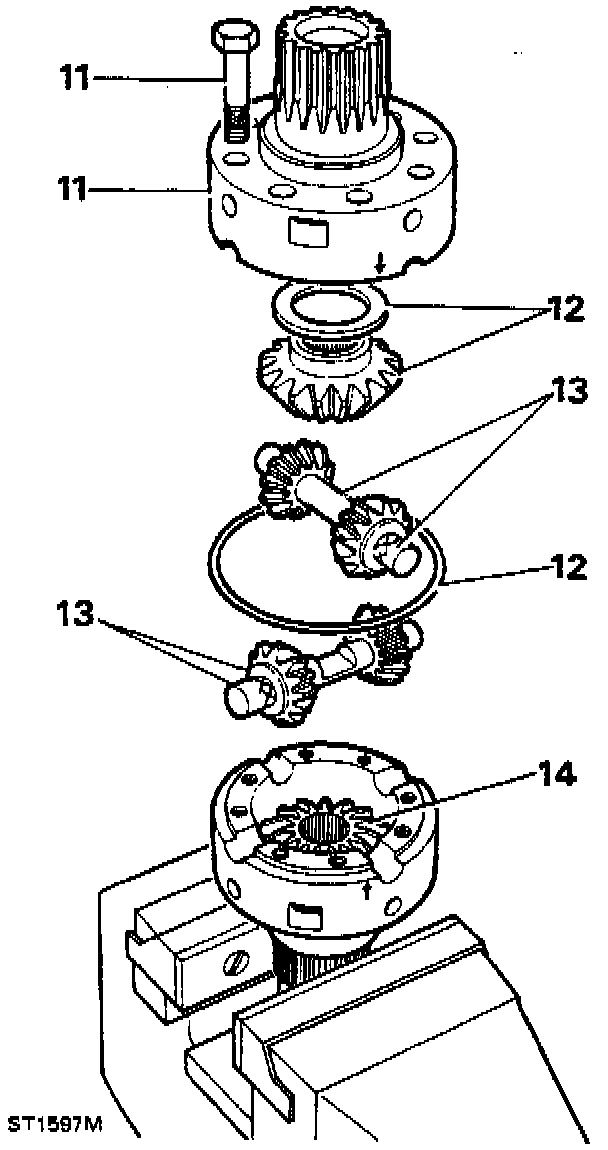
11. Remove the eight retaining bolts and lift off the front part of the differential unit.
12. Release the retaining ring and remove front upper bevel gear and thrust washer.
13. Remove the pinion gears and dished washers along with the cross shafts.
14. Remove the rear lower bevel gear and thrust washer from the rear part of the differential unit.
15. Remove the rear differential unit from the vice and clean all components.
16. Inspect all components for damage or wear, fit new components if necessary.
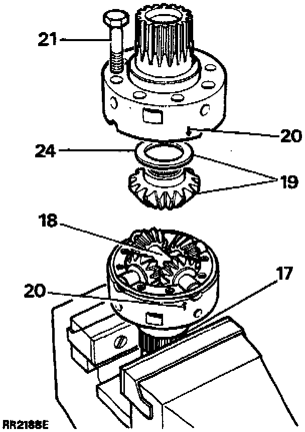
17. Using soft jaws secure the rear (longest half) of the differential unit in the vice by gripping the hub splines.
18. Lubricate and install the cross shafts and pinion gears with new dished washers. DO NOT fit the rear bevel gear at this stage.
19. Lubricate and fit the front bevel gear and thinnest thrust washer (FRC6956 1.05 mm).
20. Fit front half of the differential casing ensuring that the two engraved arrows are aligned.
21. Fit securing bolts and tighten to 55-64 Nm (40-47 ft lb).
22. Lubricate and insert the rear output shaft into the bevel gear and check that the gears are free to rotate.
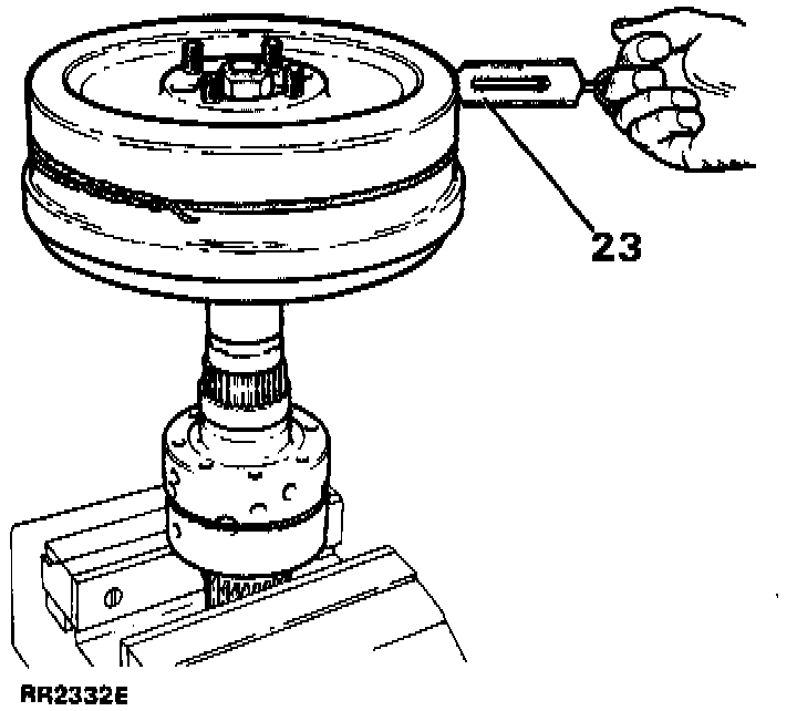
23. Fit the parkbrake drum to the output drive flange and check the torque required to rotate the gears. Tie a length of string around the brake drum, attach a spring balance to the string and carefully tension the string until a load to turn is obtained. Alternatively use a torque wrench applied to the brake drum flange nut. Rotate the drum slowly by hand to overcome initial load when using either method. Note that illustration shows checking torque at rear bevel gear.
NOTE: Gears that have been run will rotate smoothly and will require a torque of 0.56 Nm (5 in lb). Equivalent force using spring balance: 0.45 kg (1 lb). New gears will rotate with a notchy feel and will require a torque of not more than 2.26 Nm (20 in lb). Equivalent force using spring balance: 1.72 kg (3.8 lb).
NOTE: Keep all components well lubricated when carrying out these adjustments.
24. Change the thrust washer for a thicker one if the torque reading is too low. Five thrust washers are available in 0.10 mm steps ranging from 1.05 mm to 1.45 mm.
25. Dismantle the unit when the front bevel gear thrust washer is selected.
26. Remove and retain the front bevel and thrust washer combination.
27. Reassemble the unit with the rear bevel gear and thinnest thrust washer in position.
28. Using soft jaws secure the front (shortest half) of the differential unit in the vice by gripping the hub splines.
29. Repeat the above procedure to obtain the correct thrust washer for the rear bevel gear.
Re-Assembling
30. Fit the selected thrust washer and bevel gear into the rear differential unit.
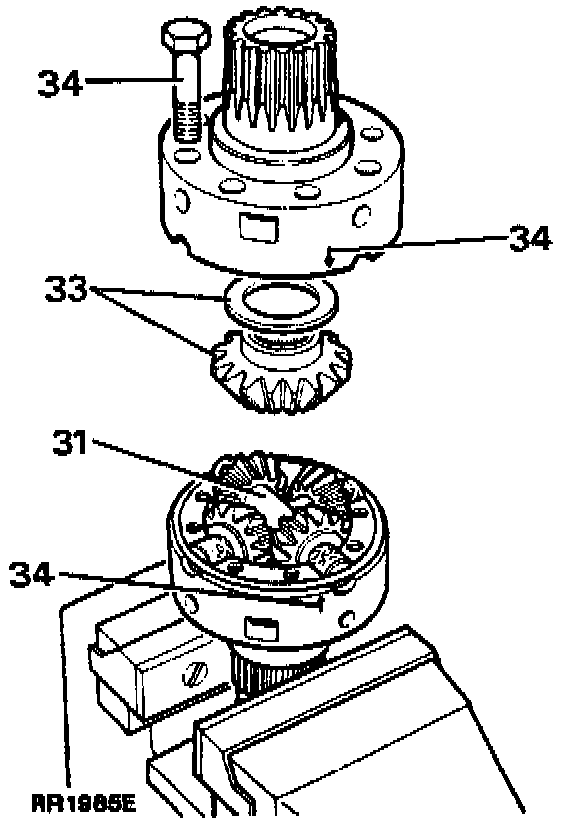
31. Assemble both pinion assemblies and dished washers on to their respective shafts and fit the rear differential unit. Secure the assemblies with the retaining ring.
32. Lubricate all the components.
33. Fit the selected thrust washer and bevel gear into the front upper differential unit.
34. Align both units as previously described and secure with the eight bolts to 55-64 Nm (40-47 ft lb).
35. Check the overall torque required to turn the differential. This should be approximately equal to the resistance of both bevel gears added together.
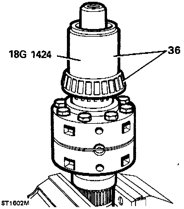
36. Locate the front differential bearing onto the front, upper differential shaft and press into position using larger end of tool 18G1424 as shown.
37. Invert the differential unit and secure in the vice.
NOTE: During the following sequences all parts should be lubricated as they are fitted.
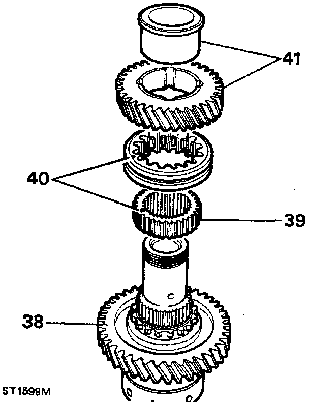
38. Fit the low range gear, with its dog teeth away from the differential assembly.
39. Press the high/low hub on to the differential splines.
40. Slide the high/low selector sleeve on to the high/low hub ensuring that the alignment marks are opposite each other.
41. Fit the bush into the high range gear so that the flange is fitted on the opposite side of the gear to the dog teeth. Slide the bushed gear on to the differential assembly with the dog teeth down.
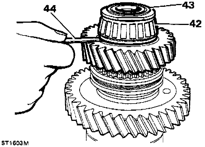
42. Locate the rear differential bearing on to the hub and press it into position using the smaller end of tool 18G1424.
43. Fit the stake nut and tighten to 66-80 Nm (50-59 ft lb) using tool 18G1423.
44. Check the end float of the high and low range gears 0.05-0.15 mm (0.002-0.006 in).
NOTE: If the clearances vary from those specified in the data at the beginning of the overhaul, the assembly must be rebuilt using the relevant new parts.
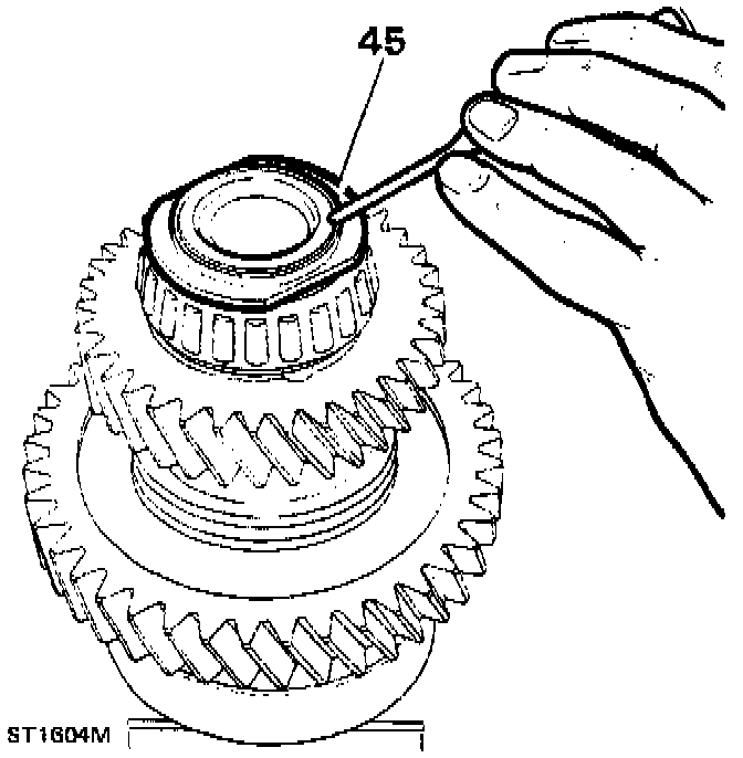
45. Peen the stake nut collar by carefully forming the collar of the nut into the slot as illustrated.
CAUTION: A round nose tool must be used for this operation to avoid splitting the collar of the nut.
46. Clean and check high/low selector fork assembly for wear and replace if necessary.
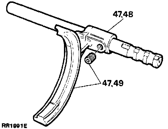
47. To replace the selector fork remove the set screw and slide the fork from the shaft,
48. Fit the new selector fork with its boss towards the three detent grooves. Align the tapped hole in the fork boss with the indent in the shaft nearest to the detent grooves.
49. Apply Loctite(r) 290 to the set screw threads and fit the set screw and tighten to 22-28 Nm (16-21 ft lb).
Centre Differential Rear Bearing Track
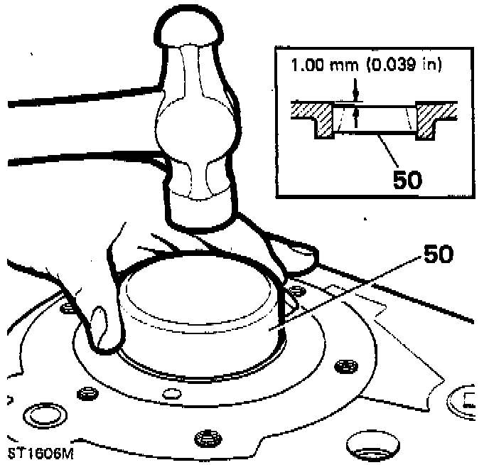
50. Fit the differential rear bearing track 1.00 mm (0.039 in) below the outer face of casing using a suitable tool as shown.