Part 2
TRANSFER CASE OVERHAUL - Part 2Rear Output Housing-Refit
1. Grease output housing gasket and position on to the rear face of the transfer box casing.
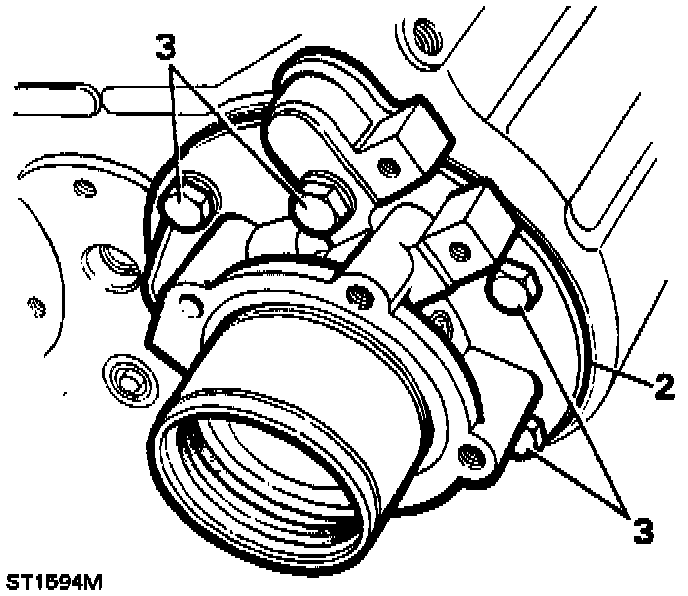
2. Fit output housing and ensure clearance of 1.00 mm (0.039 in) between housing face and gasket.
3. Fit the six output housing bolts with Loctite(r) 290 on the threads, with washers and tighten evenly to 40-50 Nm (29-37 ft lb), which will pull the rear bearing into position.
Centre Differential Unit Refit
1. Fit the selector fork/shaft assembly to the high/low selector sleeve on the differential assembly, with detent groove to the rear of the differential assembly.
2. Locate the differential assembly complete with selector fork into the transfer box casing. It may be necessary to rotate the output shaft to ease fitment, and guide selector shaft into its hole.
3. Fit selector shaft ball and spring through the side of the transfer box casing.
4. Apply Loctite(r) 290 to detent plug; fit and locate, by screwing gently fully home and then unscrewing two turns.
Front Output Housing Overhaul-Dismantling
1. Unscrew seven retaining bolts and washers and remove the differential lock selector side cover and gasket, discard the gasket.
2. Unscrew three retaining bolts and washers and lift the differential lock finger housing and actuator assembly from the front output housing.
3. Loosen the locknut and unscrew the differential lock warning light switch.
4. Remove selector shaft detent plug, spring and ball using a suitable magnet.
5. Compress the selector fork spring and remove the two spring retaining clips.
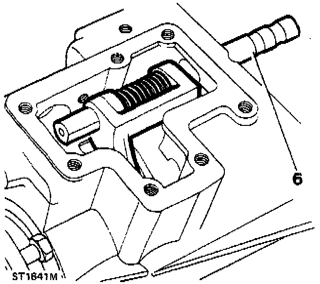
6. Withdraw the selector shaft from the rear of the output housing.
7. Remove the selector fork and spring through the side cover aperture.
8. Remove lock-up sleeve from the rear of the output housing.
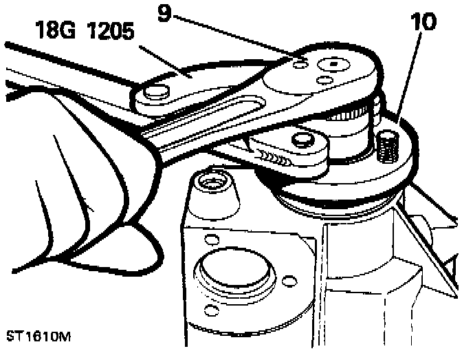
9. Using flange wrench 18G1205 and socket wrench, remove the flange nut, steel and felt washers.
NOTE: Ensure that flange bolts are fully engaged in the wrench.
10. Remove the output flange with oil seal shield.
NOTE: These parts need not be separated unless the flange bolts are to be replaced.
11. Drive output shaft rearwards from housing using a soft headed mallet.
12. Slide off the collar from the output shaft.
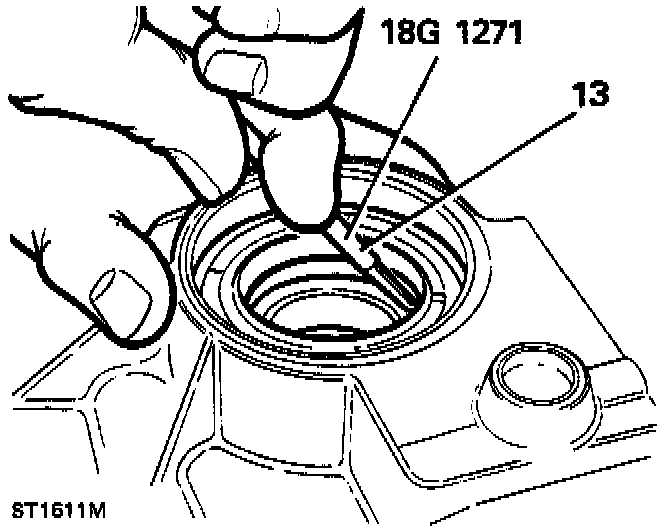
13. Pry out and discard oil seal from output housing using service tool 18G1271.
14. Remove circlip with circlip pliers 18G257.
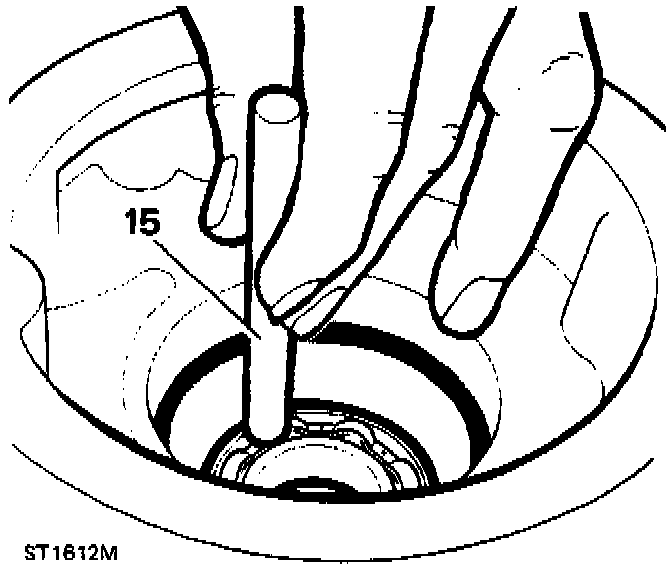
15. Invert housing and drive out bearing from inside the case as shown.
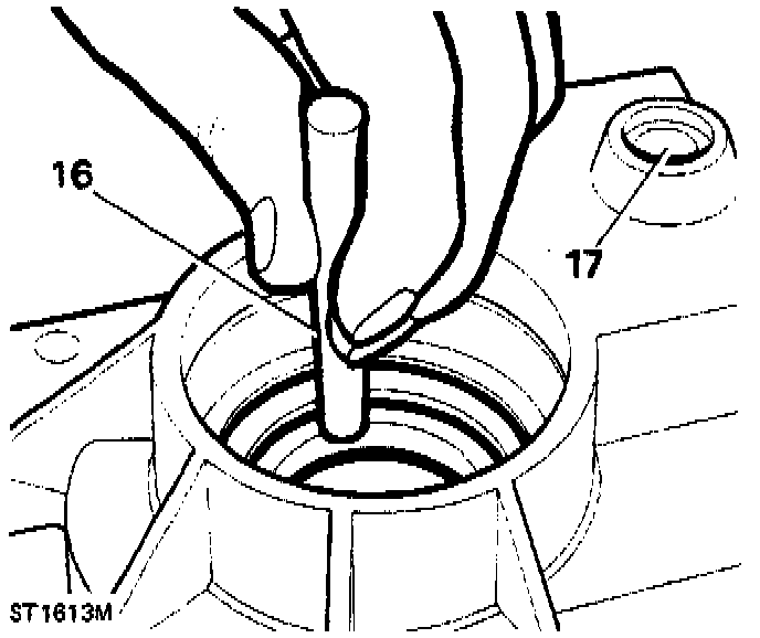
16. Drive out center differential front taper roller bearing track and shim.
17. Drive out selector shaft cup plug from housing.
18. Clean all components ensuring all traces of Loctite(r) are removed from faces and threads.
19. Examine components for wear or damage and replace if necessary.
NOTE: Replace oil seal, felt seal and flange nut.
Reassembling
20. Press the bearing into the housing; do not use excessive force. To facilitate fitting the bearing, heat the front output housing. This is not to exceed 100°C (212°F).
21. Using circlip pliers 18G257, fit the bearing retaining clips.

22. Pre-grease and fit a new oil seal (open side inwards) using replacer tool 18G1422, until the seal just makes contact with the circlip.
23. Carefully coat the lips of the seal with clean grease.
24. Slide collar on to the output shaft, with its chamfered edge away from the dog teeth.
25. Fit the output shaft through the bearing and drive home.
Adjusting Front Differential Bearing Pre-Load
26. Measure original differential front bearing track shim.
27. Refit original shim into the output housing.
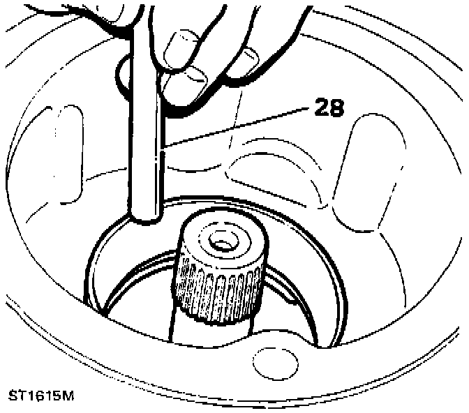
28. Drift differential front bearing track into the housing using a soft driver.
29. Grease and fit new gasket and locate the front output housing on the transfer box casing.
30. Fit the eight housing retaining bolts and washers, the upper middle bolt being longer than the rest. Do not tighten at this stage.
31. Engage high or low gear.
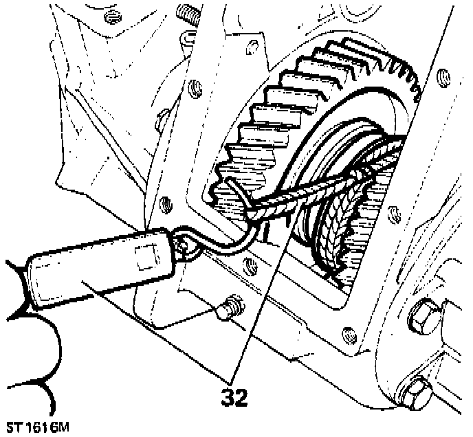
32. Check the rolling resistance of the differential using a spring balance and a length of string wound around the exposed splines of the high/low hub. With the bolts finger tight, little or no resistance should register.
33. Tighten the bolts a little at a time, occasionally checking the rolling resistance. With the correct shim fitted and the bolts tightened to the specified torque the load to turn should be 1.36 kg-4.53 kg (3 lb-10 lb).
NOTE: Alternatively, using a suitable torque wrench to achieve the torque to turn, the readings should be as follows: 0.56-1.69 Nm (5-15 in lb). The flange nut must be fitted to enable the use of a torque wrench. This applies to new or used bearings. (New bearings will register at the top end and used bearings will register at the low end).
34. If the reading is in excess of the above measurements, remove the front output housing assembly from the transfer box casing.
35. Using a suitable extractor, withdraw the center differential bearing track and change the shim for one of a suitable thickness. (A thinner shim will reduce the rolling resistance).
36. Fit the new shim and drift the differential bearing track back into its housing until fully home.
37. Having obtained the load to turn, prop-up the transfer box casing on the bench with the front face uppermost.
38. Apply Loctite(r) 290 to the threads of the housing retaining bolts and fit the eight bolts and washers into the front output housing and tighten to 22-28 Nm (16-21 ft lb).
39. Fit front output flange, felt washers, steel washers and flange nut.
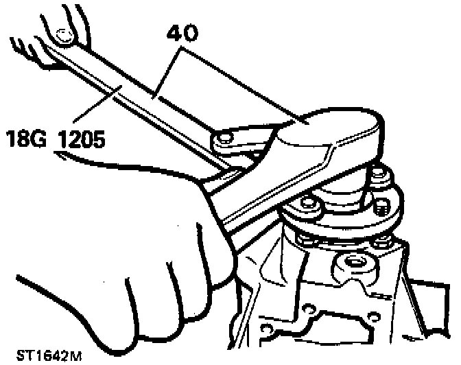
40. Using flange wrench 18G1205 and torque wrench, pull the output shaft up to the correct position. Check that the oil seal shield does not foul the housing. Ensure the nut is tightened to 146-179 Nm (108-132 ft lb).
NOTE: Ensure that the flange bolts are fully engaged in the wrench.
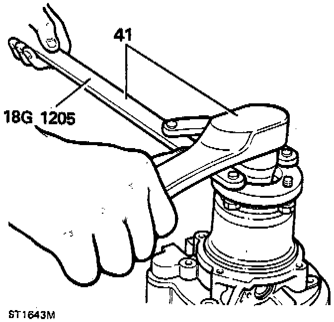
41. Repeat the above operation for the rear output flange.
42. Compress the selector shaft spring and fit to the selector fork.
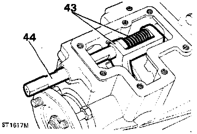
43. Locate selector fork through front output housing side cover aperture, ensuring that the fork engages in the groove of the lock-up sleeve.
44. Fit selector shaft through the aperture in the front of the output housing and pass it through the selector fork lugs and spring into the rear part of the housing.
45. Rotate the selector shaft until the two flats for the spring retaining caps are at right angles to the side cover plate face.
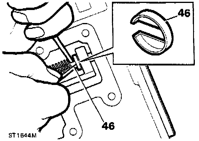
46. Compress the spring between the fork lugs and slide the retaining caps on to the shaft ensuring the spring is seated in the cupped side of the caps.
47. Apply a suitable sealant, a new seal cup, and drive the cup into position.
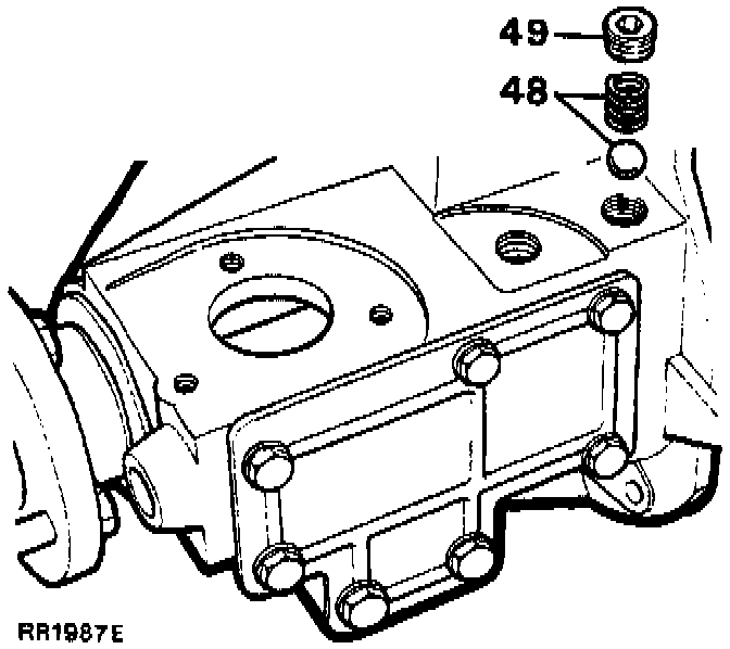
48. Fit selector shaft detent ball and spring in the tapped hole on top of the output housing.
49. Apply Loctite(r) 290 to detent plug threads. Screw detent plug gently home and then unscrew two turns.
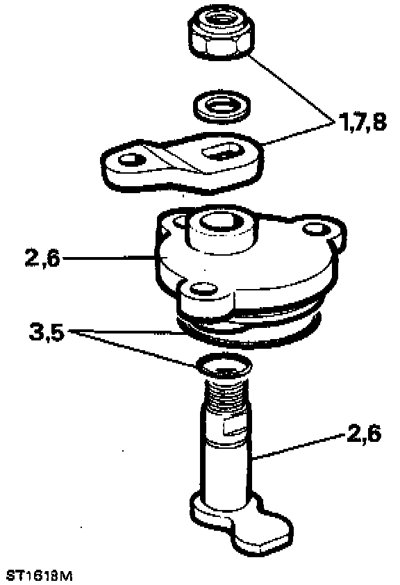
Differential Lock Finger Housing Overhaul-Dismantling
1. Unscrew and discard the Nyloc nut and remove the operating lever and washer.
2. Remove the pivot shaft from differential lock finger housing.
3. Remove the O-rings from the pivot shaft and housing and discard.
4. Clean all components; examine for wear or damage and replace if necessary.
Reassembling
5. Fit new O-rings on to pivot shaft and lock finger housing and lubricate with oil.
6. Locate the pivot shaft in the housing.
7. Fit the differential lock lever over the pivot shaft so that the lever will point forward as shown. This lever is then in the correct operating position.
8. Retain the lever with a plain washer and new Nyloc nut.
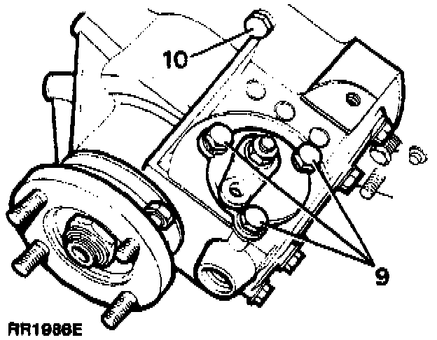
9. Fit the differential lock finger housing into its seating on the front output housing, ensuring that the selector finger is located in the flat of the selector shaft.
10. Apply Loctite(r) 290 to the bolt threads and retain the lock finger housing with the three bolts and washers to 22-28 Nm (16-21 ft lb).