Part 3
TRANSFER CASE OVERHAUL - Part 3High/Low Cross-Shaft Housing Overhaul
1. Release the locknut and remove the neutral warning switch.
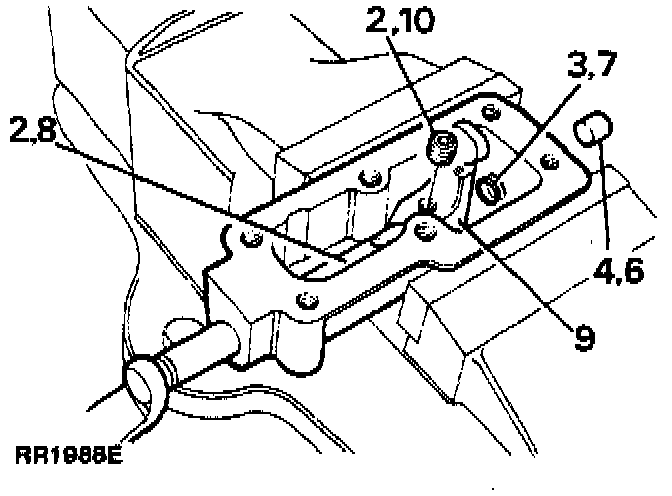
2. Remove the selector finger set screw and withdraw the cross-shaft from the cross-shaft housing and remove the selector finger.
3. Remove the O-ring from the cross-shaft.
4. Drive out selector housing cup plug if necessary.
5. Clean all the components and check for damage or wear, replace if necessary.
6. Apply sealant to a new cup plug and fit so that the cup is just below the chamfer for the cross-shaft bore.
7. Fit new O-ring to cross-shaft.
8. Lubricate the shaft and insert into the cross-shaft housing.
9. Fit selector finger ensuring that it aligns with the recess in the cross-shaft.
10. Apply Loctite(r) 290 to the set screw and secure the selector finger to the cross-shaft and fully tighten to 22-28 Nm (16-21 ft lb).
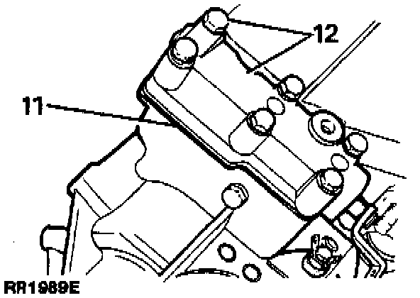
11. Grease and fit the high/low selector housing gasket on the front output housing.
12. Fit high/low cross-shaft housing, ensuring that the selector finger locates in the slot of the selector shaft, and secure with six bolts and washers to 22-28 Nm (16-21 ft lb).
Input Gear Overhaul-Dismantling
1. Clean the input gear assembly and examine for wear or damage. Remove the bearings only if they are to be replaced.
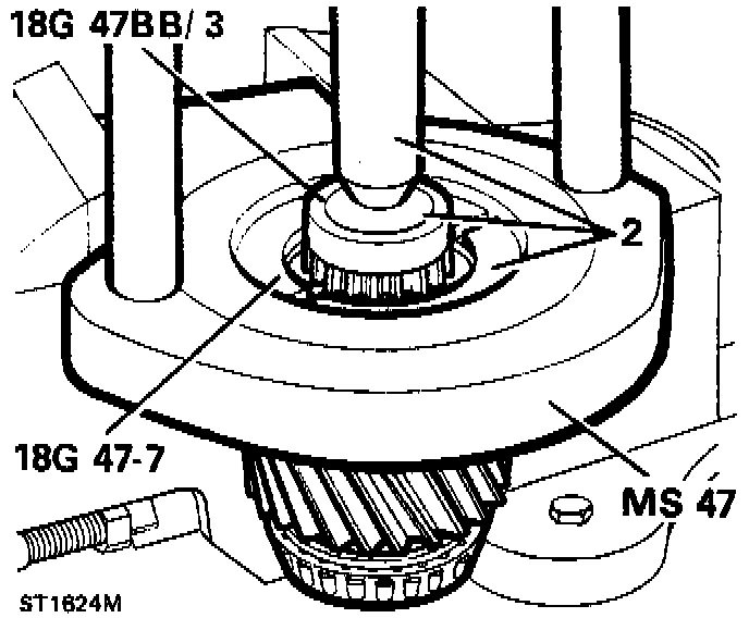
2. Secure hand press MS47 in the vice and using collars 18G47-7 and button 18G47BB3, remove rear taper roller bearing from input gear assembly.
3. Invert input gear assembly in hand press and remove front taper roller bearing.
4. Clean input gear.
Re-Assembling
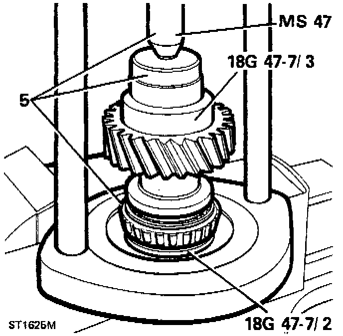
5. Position rear taper roller bearing on input gear and using hand press MS47 and collars 18G47-7 press the bearing fully home.
6. Invert input gear and fit the front taper roller bearing using the press and collars.
7. Prop up the transfer box casing on the bench with the rear face uppermost.
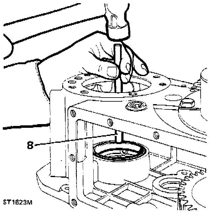
8. Drive in the front taper bearing track.
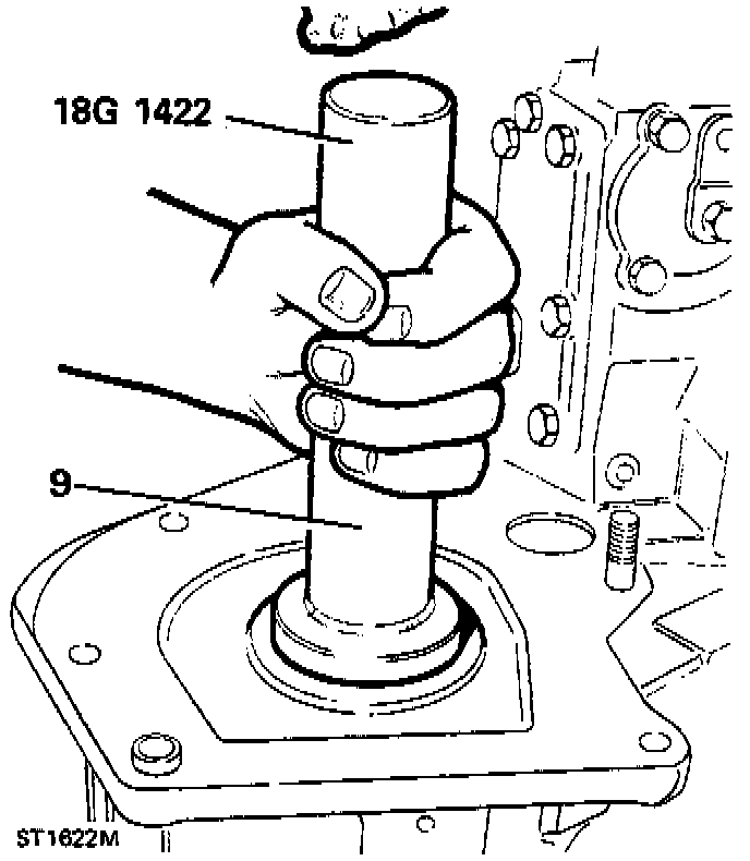
9. Reposition transfer box casing so the front face is uppermost and fit oil seal (open side inwards) using replacer tool 18G1422.
10. Lubricate both bearings with clean oil.
11. Fit the input gear assembly into the transfer box casing with the dog teeth uppermost.
Checking Input Gear Bearing Pre-Load
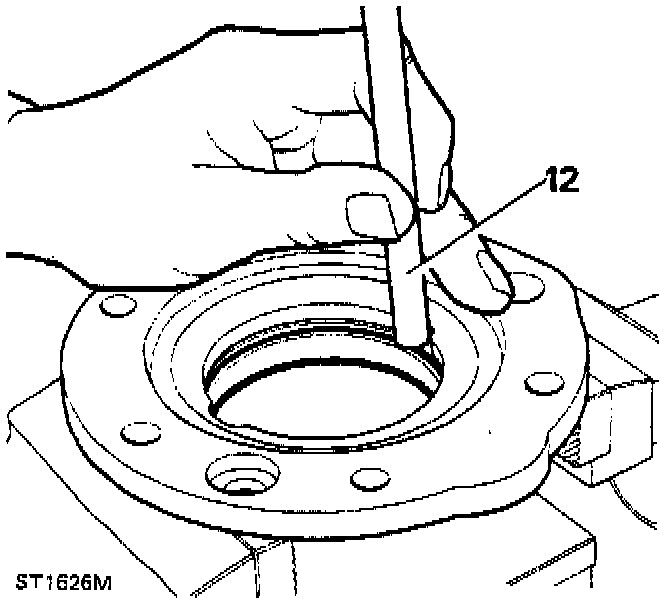
12. Secure bearing support plate in the vice. Drive out input gear bearing track, and remove shim.
13. Clean bearing support plate and shim. Measure original shim and note its thickness.
14. Fit the original shim to the support plate.
15. Locate the bearing track in the support plate and press fully home.
16. Apply grease to the gasket and fit on to the transfer box casing.
17. Fit the bearing support plate on to the transfer box casing and secure with the six bolts, but do not tighten.
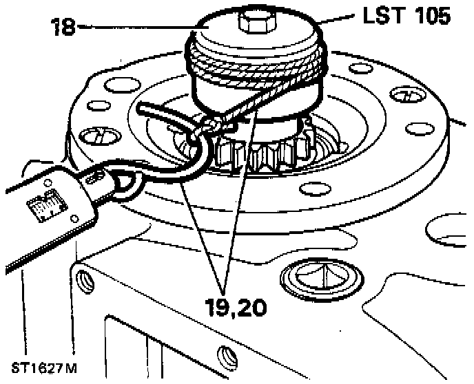
18. Fit the service tool LST105 to input gear and engage the spline.
19. Tie a length of string to the cotter pin and fit it to the service tool as shown.
20. Carefully tension the string using a spring balance, little or no resistance will be felt at this stage. Tighten the bolts a little at a time, occasionally checking the rolling resistance. With the bolts tightened to 22-28 Nm (16-21 ft lb) the rolling resistance should be 2.26 kg-9 kg (5-20 lb).
NOTE: Alternatively using a suitable torque wrench applied to the nut on the service tool, a reading for a torque to turn should be 0.56-2.25 Nm (5-20 in lb).
21. If the reading obtained is outside the above limits, the original shim must be changed.
22. Remove the spring balance, string and service tool.
23. Remove the six bolts and the bearing support plate.
24. Drive out the input gear bearing track from the support plate and discard original shim.
25. Select the correct size shim to obtain a load to turn of 0.56-2.25 Nm (5 to 20 in. lb).
26. Fit shim to support plate, locate bearing track and press home.
27. Fit bearing support plate and secure to transfer box casing with the six bolts but do not tighten.
28. Repeat the rolling resistance check as previously described, and note the value obtained.
Intermediate Gear Assembly Overhaul
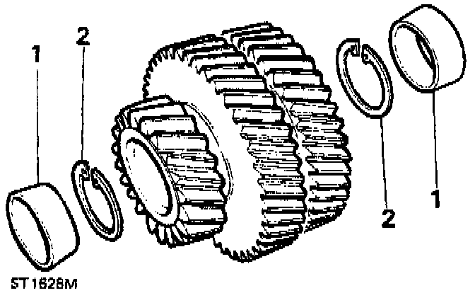
1. Drive out intermediate gear bearing tracks.
2. Remove circlips.
3. Clean all intermediate gear components and lock plate. Check for damage or wear and replace as necessary.
4. Fit new circlips into the intermediate gear cluster.
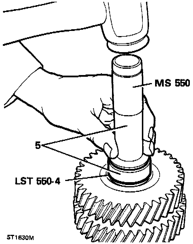
5. Using tools LST550-4 and MS550 fit bearing tracks into the intermediate gear cluster.
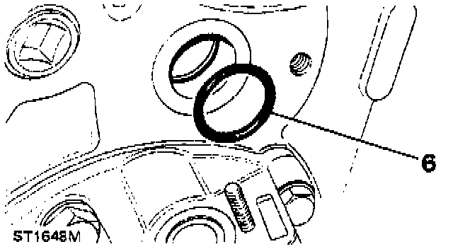
6. Fit the O-rings to the intermediate shaft and into the intermediate shaft bore at the front of the transfer box casing.
Intermediate Gear Re-Assembly
7. Check for damage to the intermediate shaft thread and if necessary clean up with a fine file or stone.
8. Lubricate the taper roller bearings and intermediate gear shaft.
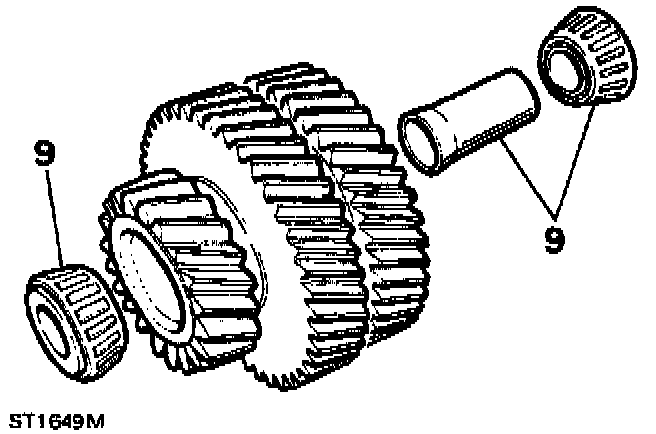
9. Insert new bearing spacer to gear assembly, followed by the taper roller bearings.
10. Fit dummy shaft LST104 into the intermediate gear cluster.
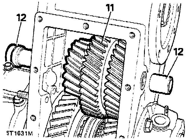
11. Locate the gear assembly into the transfer box casing from the bottom cover aperture.
12. Insert intermediate shaft from the from of the transfer box casing, pushing the dummy shaft right through as shown and remove. (Making sure that the intermediate gear cluster meshes with the input gear and higher range and low range gears).
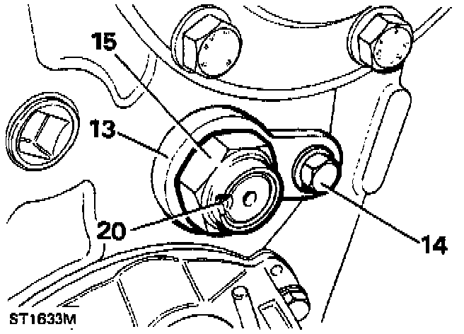
13. Turn the intermediate shaft to allow fitting of retaining plate.
14. Fit retaining plate and secure with retaining bolt and washer.
15. Fit the intermediate gear shaft retaining stake nut. Do not tighten at this stage.
Adjusting Intermediate Gear Torque-to-Turn
16. Select neutral.
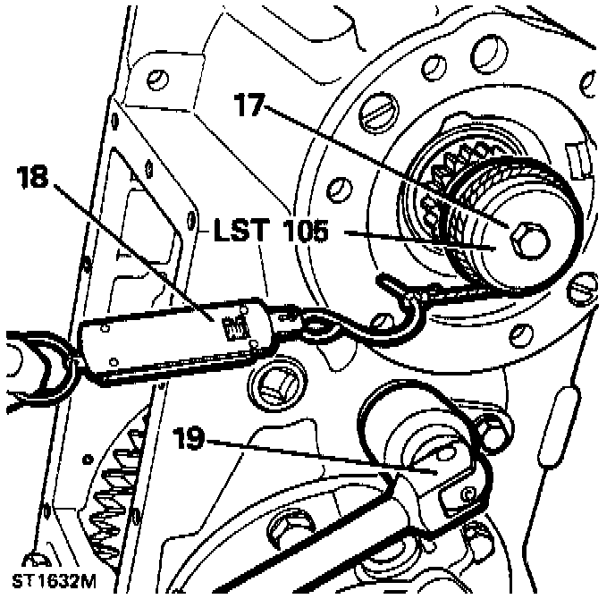
17. Fit service tool LST105 to input gear and engage spline.
18. Tie a length of string to a cotter pin and fit to the service tool as shown. Attach the spring balance to the string.
19. To obtain the correct figures and to collapse the spacer within the intermediate gear cluster, tighten the intermediate shaft nut until the load-to-turn has increased by 3.7 kg (7 lb) to 1.63 kg (+ 3 lb) on that noted when checking input shaft load-to-turn.
20. Peen the stake nut by carefully forming the collar of the nut into the intermediate shaft recess, as illustrated.
CAUTION: A round nose tool must be used for this operation to avoid splitting the collar of the nut.
Power Take-Off Cover-Reassemble
21. Clean power take-off cover and gasket face.
22. Fit the two countersunk screws and tighten.
23. Remove the six bolts from the bearing support plate.
24. Apply sealant to the cover plate gasket and fit it to the bearing support plate.
25. Apply Loctite(r) 290 to bolt threads and secure the power take-off cover with the six bolts and washers to 40-50 Nm (29-37 ft lb).
Bottom Cover-Reassemble
26. Clean bottom cover and gasket face.
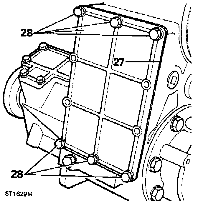
27. Apply sealant to cover gasket and fit to transfer box casing.
28. Apply Loctite(r) 290 to bolt threads and secure the bottom cover with six bolts and washers to 22-28 Nm (16-21 ft lb).
Differential Lock Switch Adjustment
1. Select differential locked position by moving the differential lock lever towards the right side of the transfer box casing.
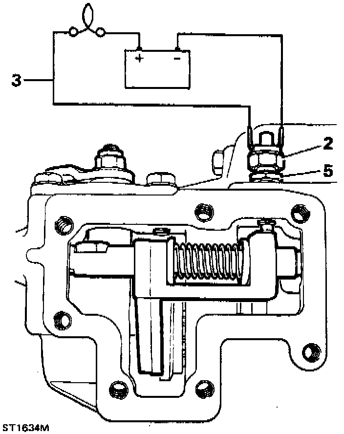
2. Apply sealant to the differential lock warning light switch and fit to the top of the front output housing.
3. Connect a test lamp circuit to the differential lock switch.
4. Screw in the lock switch until the bulb is illuminated.
5. Turn in the switch another half a turn and tighten with the locknut against the housing.
6. Disconnect the battery and move the differential lock lever to the left to disengage differential lock.
7. Clean the front output housing side cover.
8. Grease and fit side cover gasket.
9. Apply Loctite(r) 290 to bolt threads, fit side cover and secure with seven bolts and washers to 22-28 Nm (16-21 ft lb).
Neutral Warning Switch Adjustment
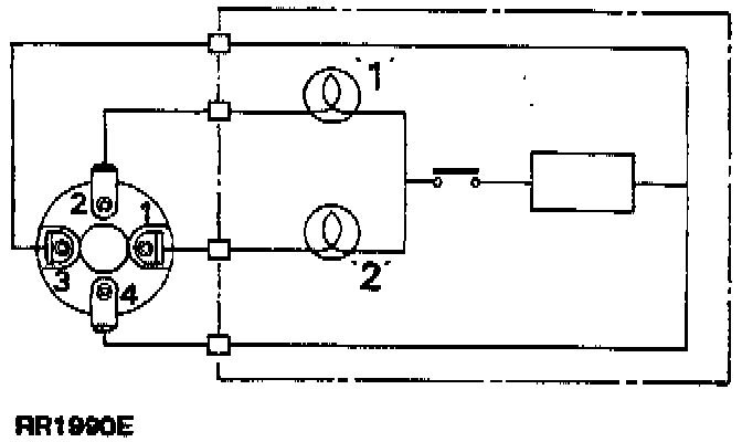
1. Connect suitable test equipment as shown.
2. Fit the switch and neutral warning switch locknut ensuring correct setting for switch.
3. To attain the correct setting the following procedure is applied:
4. Screw the switch in until test lamp 1 is extinguished.
5. Screw in switch a further 1/3 to 1/2 turn.
6. Lock switch in position using locknut.
7. Select Low Range test lamp 1 should illuminate. Select High Range test lamp 2 should illuminate. Select neutral both test lamps should extinguish.
8. If adjustment is satisfactory remove the test equipment.
Parking Brake Drum-Reassemble
1. Clean brake backplate and oil catcher and apply sealant to the catcher joint face.
2. Locate brake backplate on the rear output housing with the brake operating lever on the right side of the transfer box casing.
3. Secure the backplate (including the oil catcher) with the four special bolts and tighten using a hexagonal socket to 22-28 Nm (16-21 ft lb).
4. Clean and fit brake drum and secure with two countersunk screws to 22-28 Nm (16-21 ft lb).
5. Adjust the parking brake.