Heater Core and Evaporator Core Housing
Heater Core and Evaporator Core Housing
This is a "Trustmark Authoring Standards (TAS) Repair Procedure"
- TAS style procedures can be identified by steps that have no accompanying step text and the magenta color of the electrical connectors and fasteners such as nuts, bolts, clamps or clips.
- TAS removal and installation procedures use a sequence of color illustrations to indicate the order to be followed when removing/disassembling or installing/assembling a component.
- Many of the TAS procedures will have the installation information within the removal steps.
- The TAS color illustrations use a variety of symbols to indicate important details of the procedures. It is important to understand these symbols in order to properly used the TAS procedures.
Refer to How to Use TAS Procedures and TAS Symbol Glossary at Vehicle | Description and Operation for additional information on these TAS procedures.
For additional information, refer to How to Use TAS Procedures How to Use TAS Procedures
Removal
1 Make the SRS system safe.
2 Remove the instrument panel.
For additional information, refer to Instrument Panel - 2.2L Diesel
For additional information, refer to Instrument Panel - 3.2L Instrument Panel
3 Remove the clockspring.
For additional information, refer to Clockspring Service and Repair
4 Remove the instrument cluster.
For additional information, refer to Instrument Cluster Service and Repair
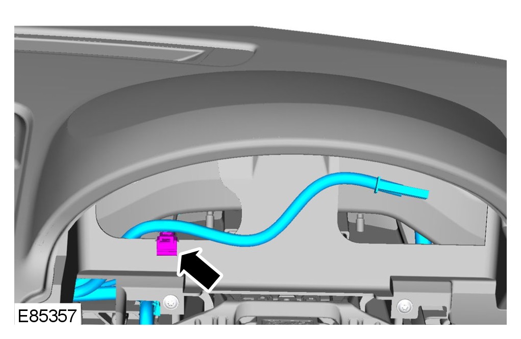
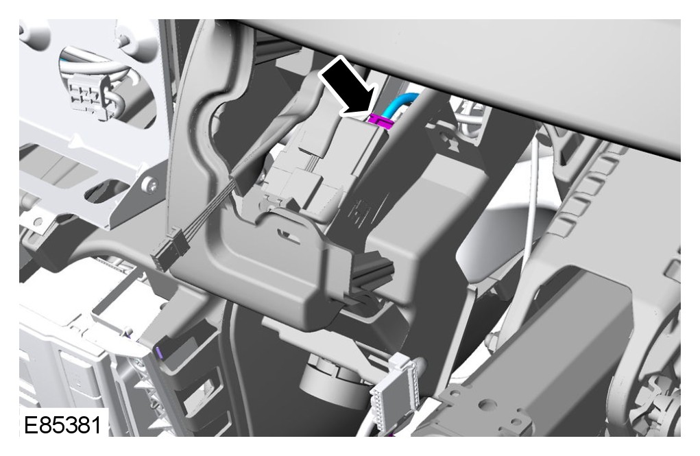
5 Disconnect the keyless start module electrical connector.
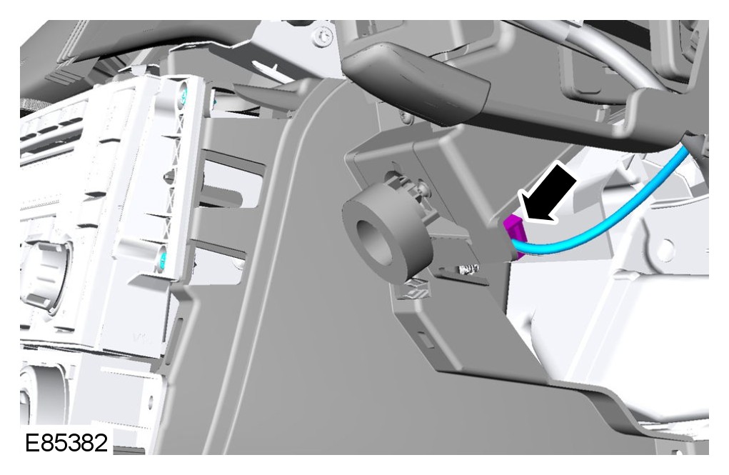
6 Disconnect the in-vehicle temperature sensor.
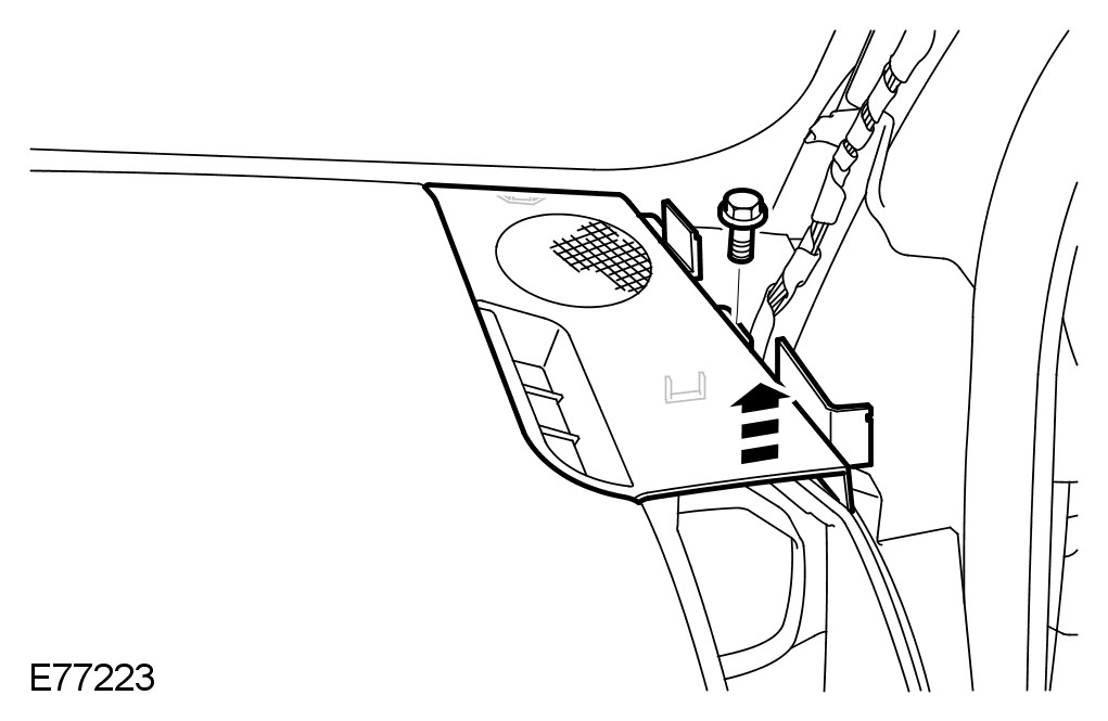
7 Remove both upper trim panels.
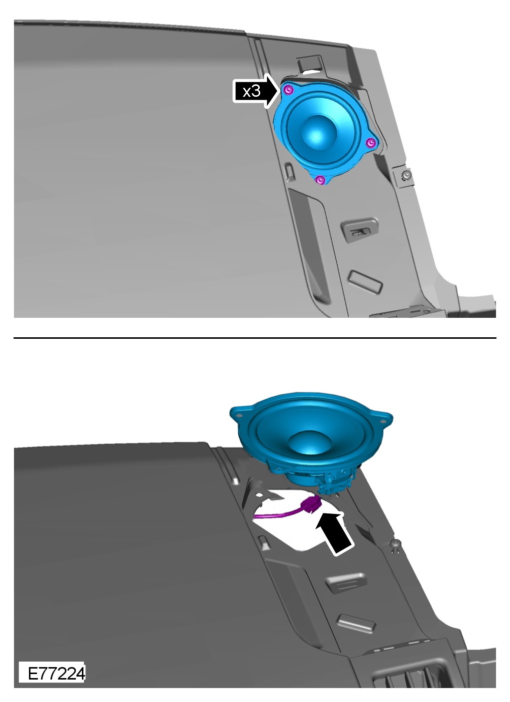
8 Remove both instrument panel speakers.
9 Remove the video display.
For additional information, refer to Video Display Service and Repair
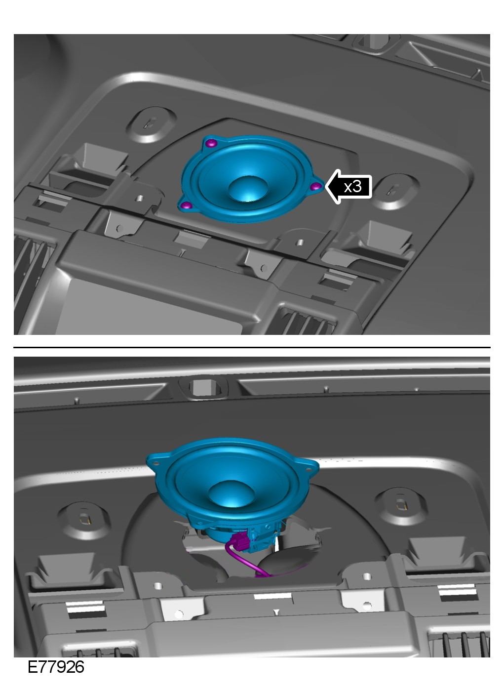
10 Remove the center speaker.
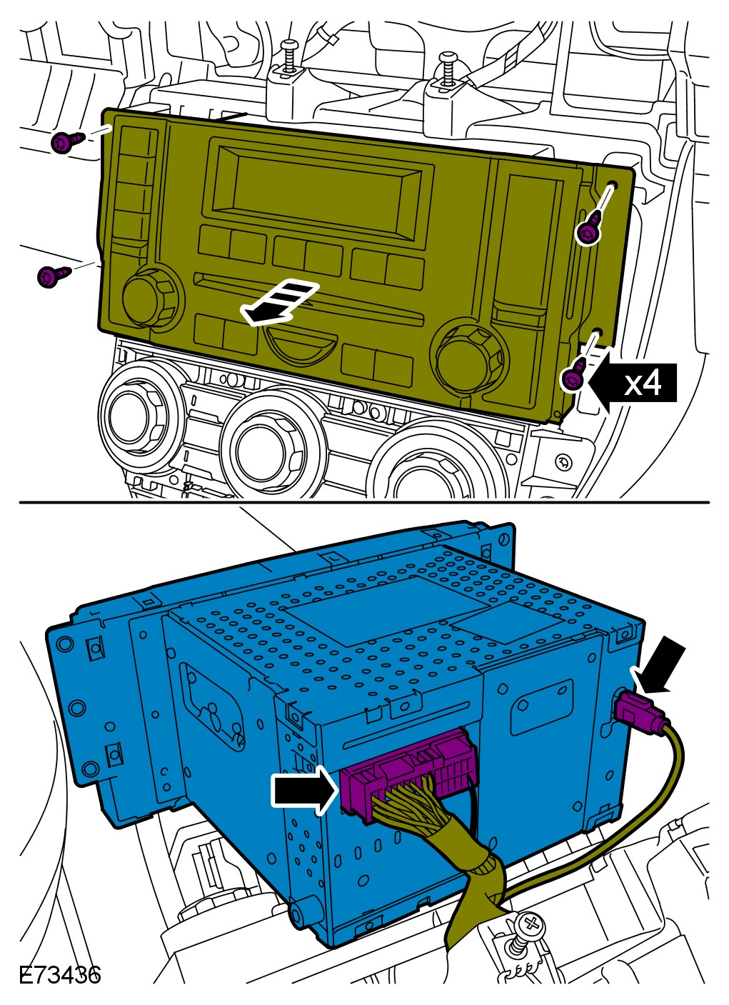
11 Remove the audio unit.
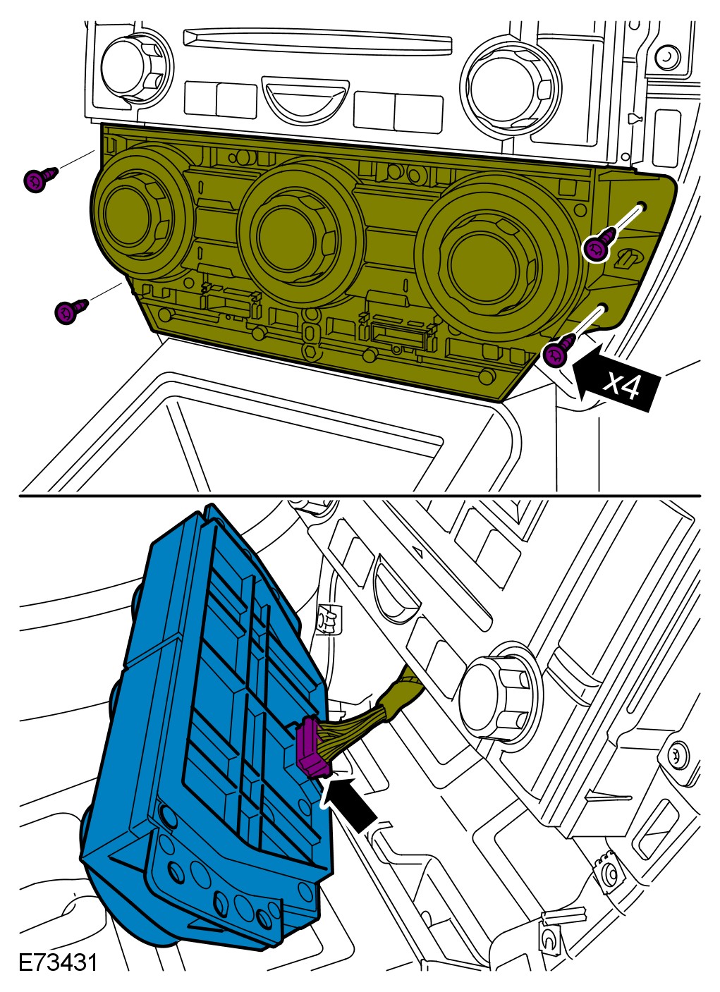
12 Remove the climate control assembly.
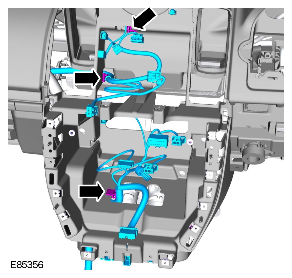
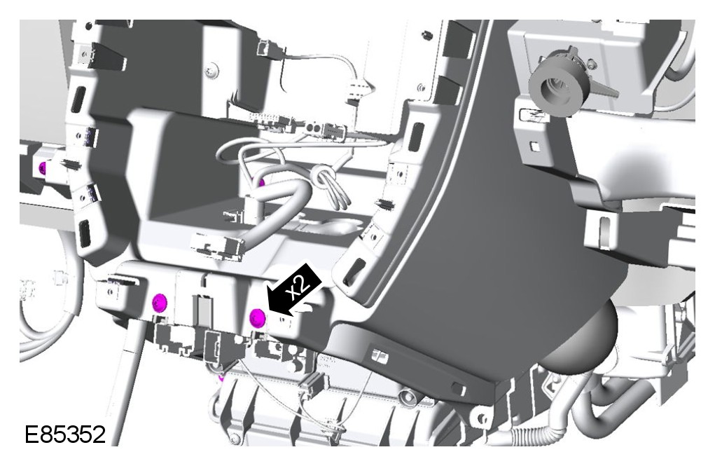
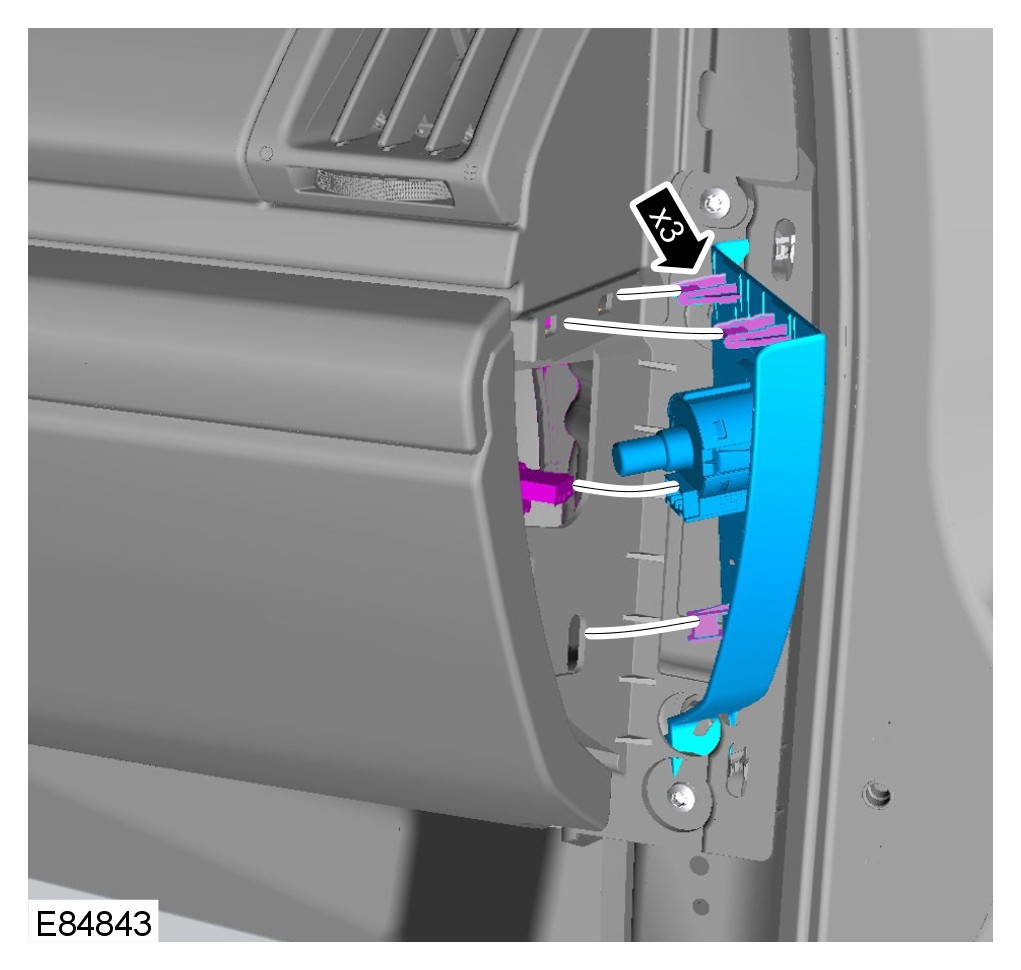
13 Remove the passenger side instrument panel end trim panel.
14 Remove the glove compartment.
For additional information, refer to Glove Compartment Service and Repair
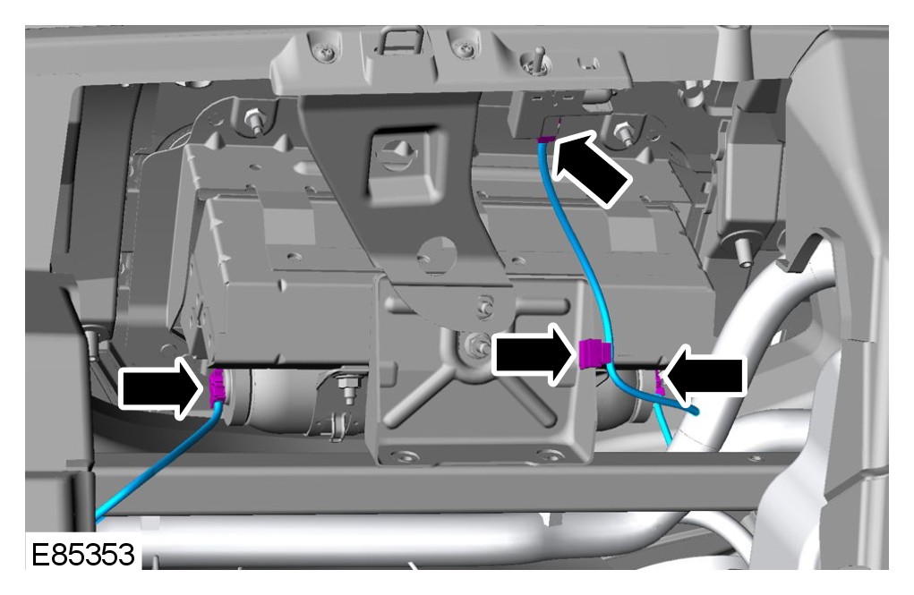
15 Release the wiring harness from the instrument panel upper section.
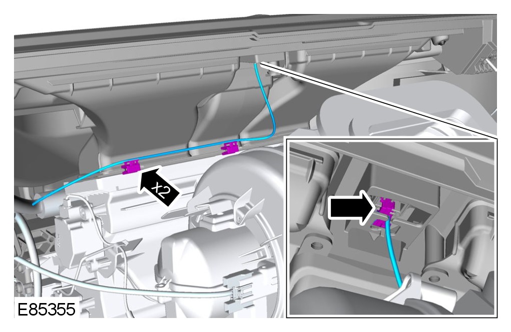
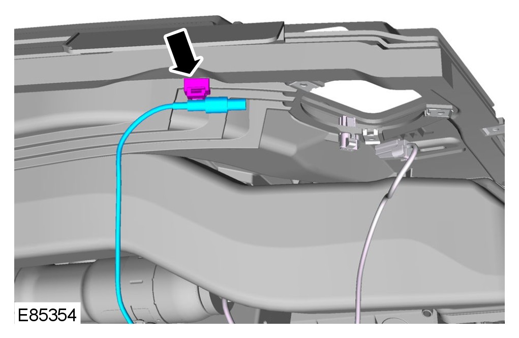
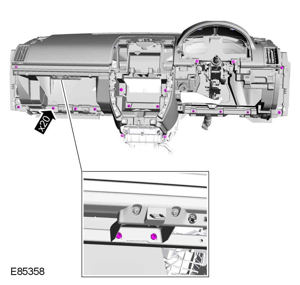
16 With assistance, remove the instrument panel upper section.
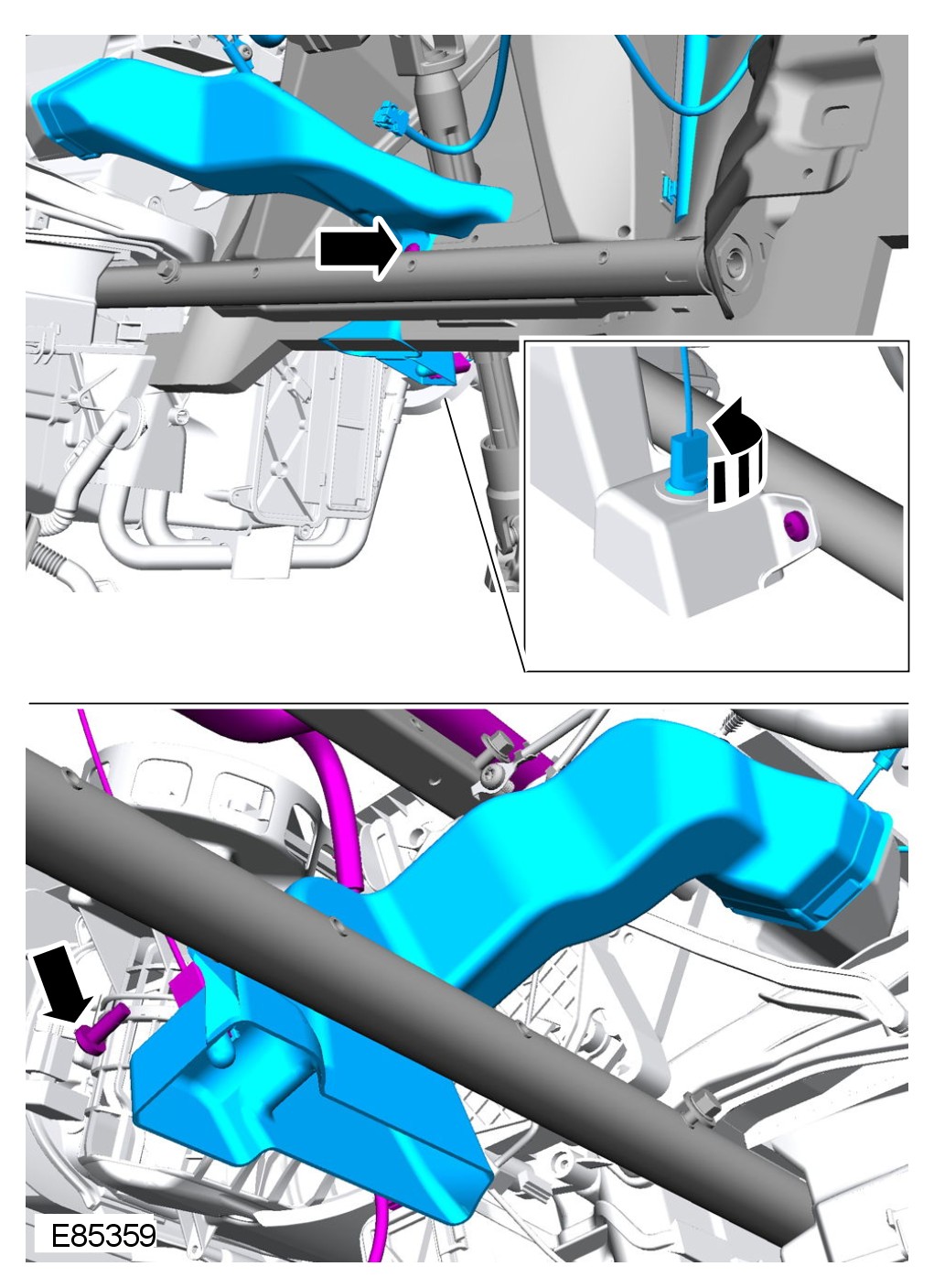
17 Remove both front footwell ducts.
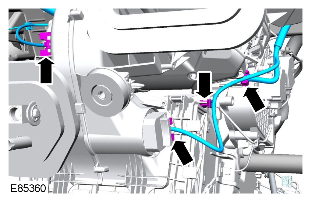
18 Disconnect the wiring harness from the heater core and evaporator core housing.
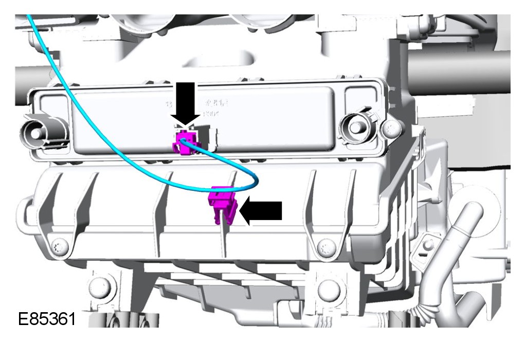
19 Disconnect the electric booster heater core.
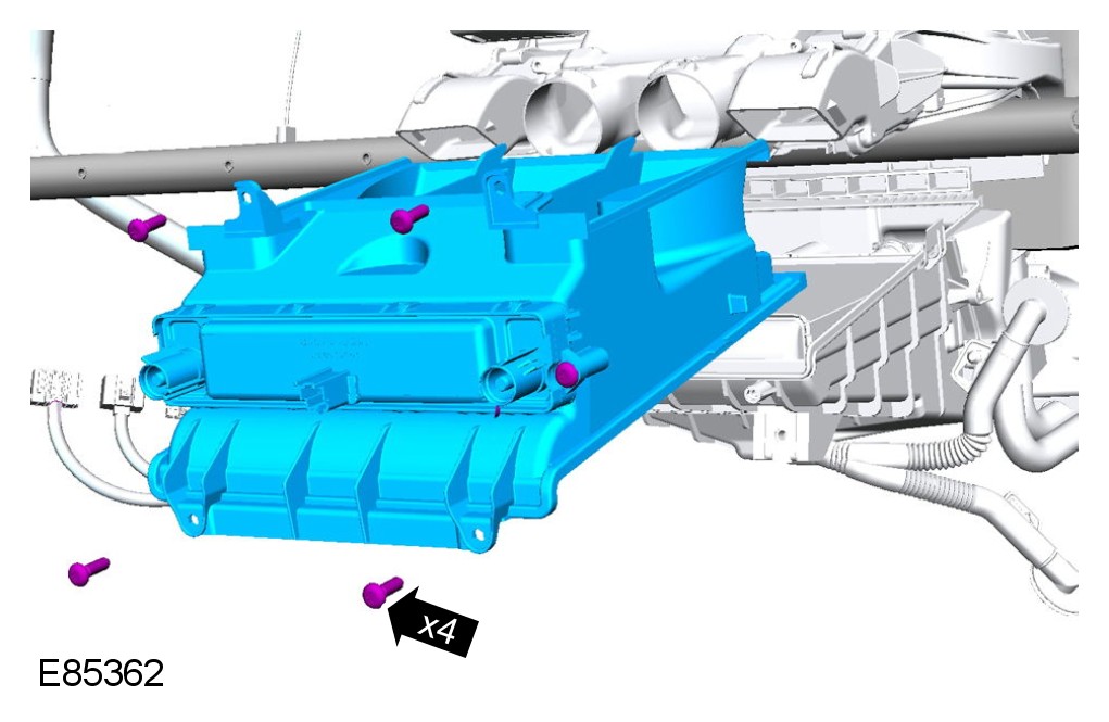
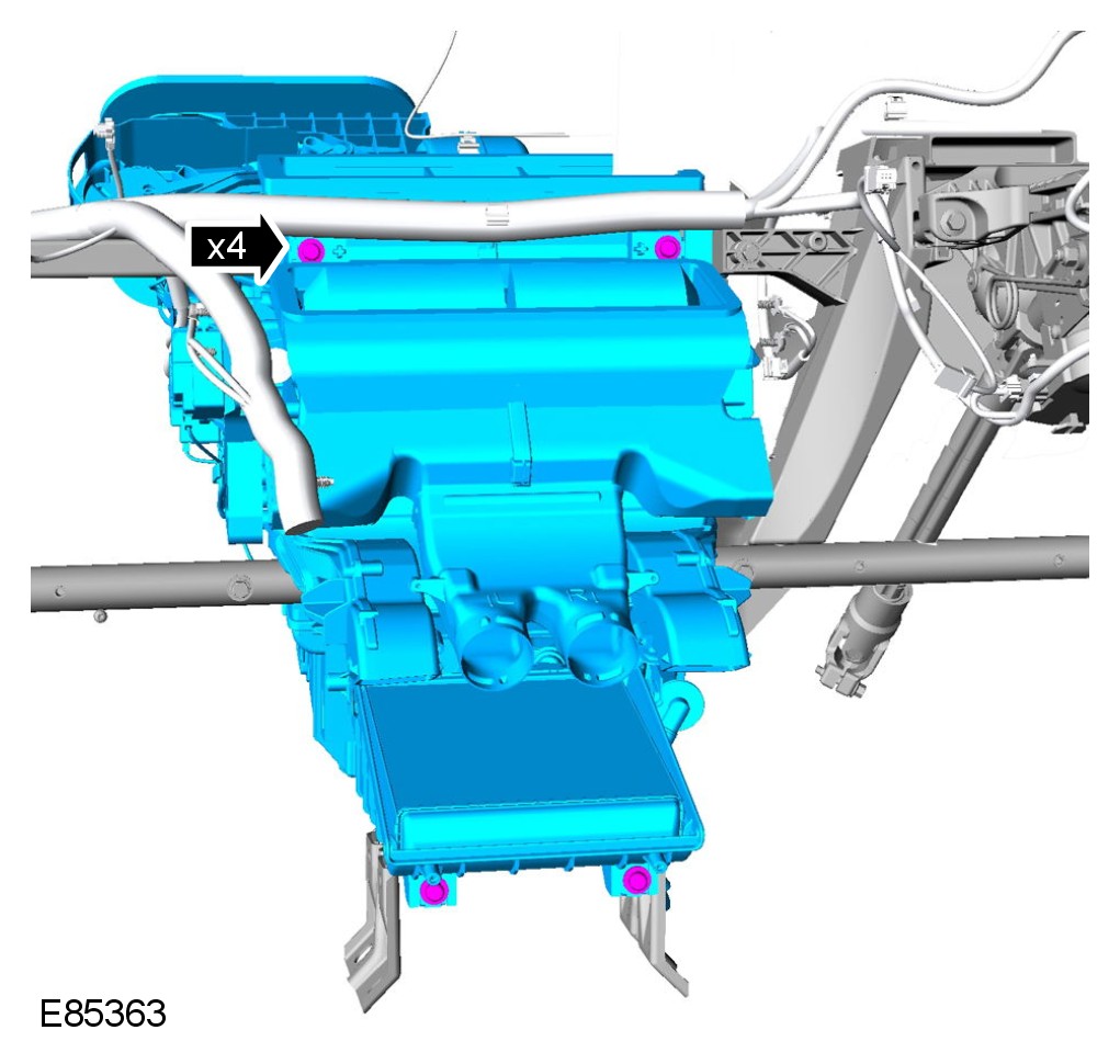
20 Remove the heater core and evaporator core housing.
Installation
1 Install the heater core and evaporator core housing.
Torque to: 7 Nm
2 Install the electric booster heater assembly.
3 Connect the electric booster heater core.
4 Connect the wiring harness to the heater and evaporator core housing.
5 Install both front footwell ducts.
6 With assistance, install the instrument panel upper
section.
7 Install the passenger air bag module support bracket bolts.
Torque to: 10 Nm
8 Secure the wiring harness to the instrument panel upper section.
9 Connect the passenger air bag module electrical connectors.
10 Install the glove compartment.
For additional information, refer to Glove Compartment Service and Repair
11 Install the passenger side instrument panel end trim panel.
12 Secure the wiring harness support bracket.
13 Install the
climate control assembly.
14 Install the audio unit.
15 Install the center speaker.
16 Install the video display.
For additional information, refer to Video Display Service and Repair
17 Install both instrument panel speakers.
18 Install both upper trim panels.
19 Connect the in-vehicle temperature sensor electrical connector.
20 Connect the keyless start module electrical connector.
21 Install the instrument
cluster.
For additional information, refer to Instrument Cluster Service and Repair
22 Install the clockspring.
For additional information, refer to Clockspring Service and Repair
23 Install the instrument panel.
For additional information, refer to Instrument Panel - 2.2L Diesel
For additional information, refer to Instrument Panel - 3.2L Instrument Panel
24 Connect the battery ground cable.
For additional information, refer to Specifications Vehicle Jump Starting
25 Return the steering column to its original position.