Load Leveling System - Height Adjustment Procedure
88ford14
Article No. 88-13-5
SUSPENSION - REAR - LOAD LEVELING RIDE HEIGHT ADJUSTMENT PROCEDURE
SUSPENSION - REAR - VEHICLE LOW IN REAR WHEN LOADED - LOAD LEVELING SYSTEM
LINCOLN-MERCURY: 1987-88 LINCOLN TOWN CAR
ISSUE: A rear load leveling system that does not rise correctly may allow the rear of the vehicle to sit 1" to 1.5" (25 to 38 mm) lower than normal when loaded with about 300 to 350 lbs. Improper vehicle height may be caused by a load leveling system that is not adjusted properly.
ACTION: To correct this, check the suspension "D" dimension curb ride height using the following service procedure. Refer to the appropriate model year Car Shop Manual, Volume A, Section 14- 32 for detailed service information.
NOTE: THE SUSPENSION HEIGHT "D" DIMENSIONS ARE FOR REFERENCE ONLY. THE VEHICLE ATTITUDE MUST BE CONTROLLED BY THE BUMPER TO GROUND DIMENSIONS SHOWN IN THE GENERAL SPECIFICATION MANUAL, SECTION 1.
"D" Dimension Curb Ride Height Checking
Procedure
1. Position the vehicle on a level surface at curb height.
2. Make sure the fuel tank is full, all engine fluids are full, and the spare tire, wheel and jack are in their proper place. Position the front seat as far rearward as possible.
3. Rock the vehicle sideways to remove the effect of suspension friction, and allow it to settle.
4. Perform the "AIR CHECK, RESIDUAL" procedure on the vehicle. Refer to the appropriate model year Car Shop Manual, Volume A, Section 14-37.
FIGURE 5:
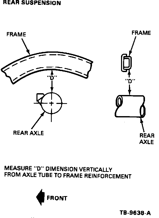
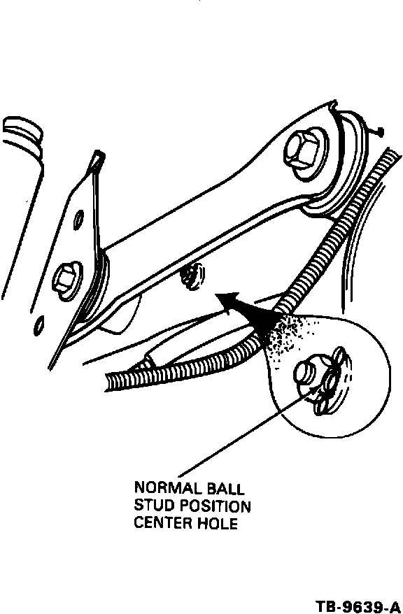
FIGURE 6:
5. Perform the "SYSTEM OPERATION CHECK" procedure on the vehicle. Refer to the appropriate model year Car Shop Manual, Volume A, Section 14-37. Step 1 of this procedure states "recommended curb height". To determine, measure "D" dimension vertically from axle tube to frame reinforcement. See Figure 5.
6. For Step 3b of this "SYSTEM OPERATION CHECK" procedure, DO NOT refer to the diagnosis selection chart; instead, "MAINTAIN STATIC LOAD APPLIED" and perform "ADJUSTMENT RIDE HEIGHT" procedure in Section 14-37. See Figure 6. After ball stud upward adjustment, with the ignition switch "ON", the vehicle should rise to within 1/2" (13 mm) of the initiap"D" dimension measurement in Step 5. See Figure 5.
FIGURE 7:
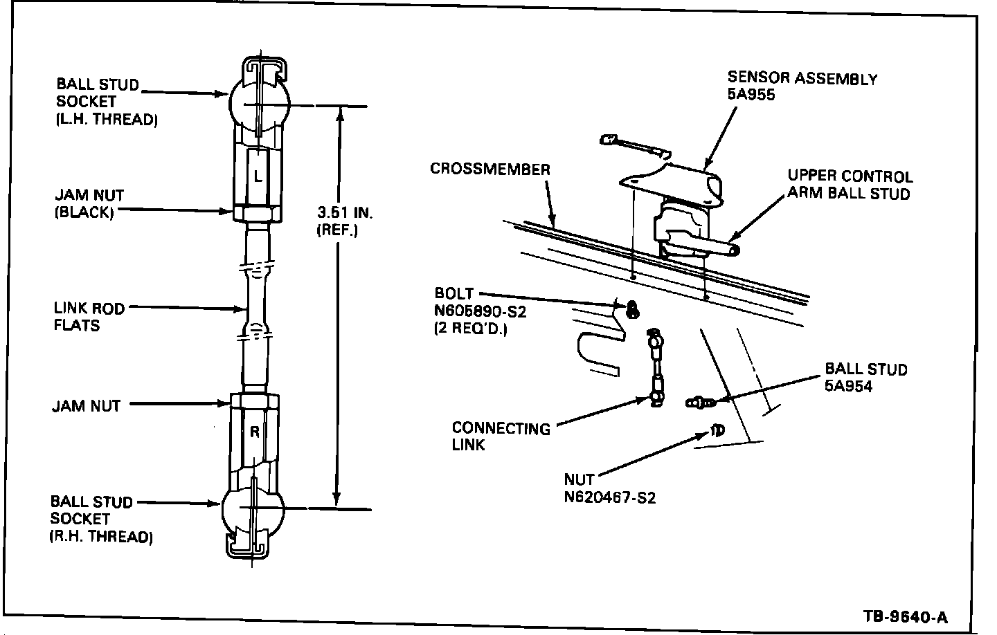
7. If the vehicle fails to return (STATIC LOAD APPLIED) within 1/2" (13 mm) of initial "D" measurement after ball stud adjustment in Step 6, adjust height sensor connecting link length with applied load as follows:
NOTE: THE CONNECTING LINK MUST REMAIN INSTALLED ON THE BALL STUDS WHEN LINK ROD ADJUSTMENT IS MADE, FIGURE 7.
a. Hold rod on flats stationary, and loosen both jam nuts.
b. Rotate the link rod clockwise (as viewed from under vehicle). One rod rotation (360~ around) will allow about 1/4" (6 mm) change up to the "D" dimension.
c. Adjust rod (5 turns MAX.) so vehicle rises to within 1 /2" (13 mm) of measurement made in Step 6. Torque both jam nuts to 15-21 in.lbs. (1.7-2.4 N-m). Additional turns will result in inadequate rod thread engagement (3.5 threads minimum) into each ball stud socket.
8. Continue with Step 4 of the "SYSTEM OPERATION CHECK" procedure in the appropriate Car Shop Manual, Volume A, Section 14-37.
OTHER APPLICABLE ARTICLES: None
WARRANTY STATUS: Eligible Under Basic Warranty Coverage
OPERATION: 881305A
TIME: 0.7 Hr.
DLR. CODING: Basic Part No. 5A955
Condition Code: 07