Lower
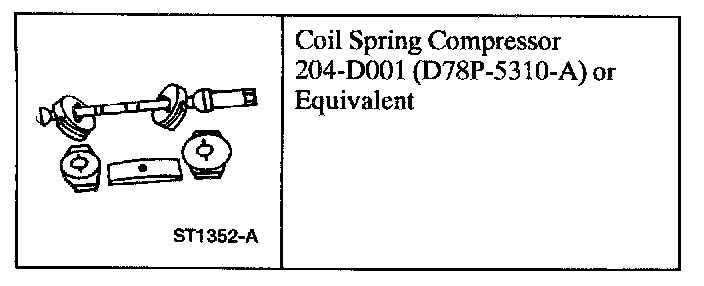
Removal
1. Raise the vehicle.
2. Remove the wheel and tire assembly.
3. Remove and discard the caliper anchor bracket retaining bolts. Lift the disc brake caliper and anchor bracket off the front brake disc and secure it out of the way. Mark the relation of the brake disc to the stud and remove the brake disc.
4. WARNING: ALL VEHICLES ARE EQUIPPED WITH GAS-PRESSURIZED FRONT SHOCK ABSORBERS WHICH WILL EXTEND UNASSISTED. DO NOT APPLY HEAT OR FLAME TO THE FRONT SHOCK ABSORBER TUBE.
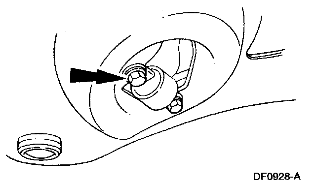
Remove the two bolts attaching the front shock absorber to the lower suspension arm.
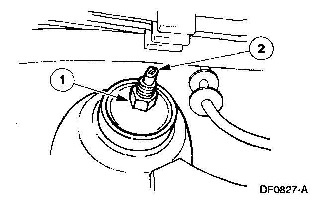
5. Remove the shock absorber.
1. Remove the nut, retainer and grommet.
2. Remove the shock absorber.
6. Remove the front suspension bumper from the lower suspension arm and inspect it. If necessary, install a new bumper during installation.
7. CAUTION: To prevent injury, do not remove the nut from the ball joint stud at this time.
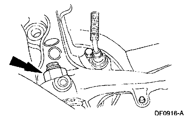
Loosen the lower ball joint retaining nut one or two turns. Separate the lower ball joint from the front wheel spindle.
8. Note: The tang on the lower ball must nest in the slot of the lower support plate. The pin in the upper ball and the tang on the lower ball prevent the support plates and threaded rod from turning under load.
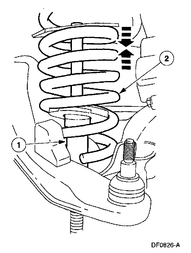
Compress the coil spring.
1. Using Coil Spring Compressor D78P-5310-A or equivalent, install the first plate midway in the spring with the ball cavity positioned up. Install the second support plate (same size) as close to the bottom of the spring as possible, with the ball cavity positioned down. Place the threaded rod through the support plates (cross hole end first). Install the upper ball between the coils of the spring, above the upper support plate and over the threaded rod. Align the holes in the upper ball with the cross hole in the threaded rod and install the pin. Lay the upper ball down into the upper support plate ball cavity so the pin nests in the slot of the plate. Wind the upper support plate up to the top of the spring, using the threaded rod as a driver. Slip the lower ball onto the threaded rod from the end, passing through the shock absorber opening and seating in the lower support plate ball cavity. Place the thrust bearing on the threaded rod and follow with the barrel nut (threaded end first).
2. Use a 1/2-inch wrench on the flats of the threaded rod to hold the threaded rod. Use a 1-1/4-inch wrench to turn the barrel nut and compress the spring until it begins to rotate.
9. Remove the ball joint retaining nut. Separate the lower suspension arm and remove from the steering knuckle. Discard the retaining nut.
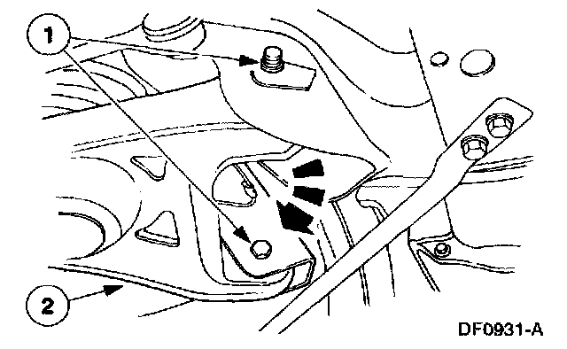
10. Remove the coil spring.
1. Loosen the lower suspension arm pivot bolts and nuts.
2. Lower the arm and remove the coil spring, with the compressor tool attached.
11. Remove the lower suspension arm pivot bolts and nuts. Disengage the lower suspension arm from the frame crossmember and remove the arm.
Installation
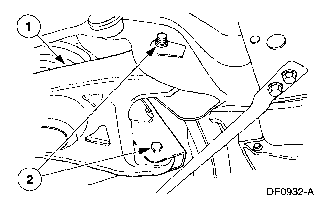
1. Install the lower suspension arm.
1. Position the lower suspension arm into the frame brackets.
2. Loosely install the bolts and nuts.
2. Position the coil spring and compressor into the lower suspension arm. Raise the lower suspension arm and install a new ball joint retaining nut. Tighten the nut to 174 Nm (128 ft. lbs.).
3. Note: The skirt can be removed from the nut, provided a load of 270 Nm (200 ft. lbs.) can be generated between the ball joint and the spindle taper. Make sure the pigtail of the lower coil of the front coil spring is in the correct location of the front spring insulator on the front lower suspension arm, between the two holes.
Remove the coil spring compressor.
4. Install the front suspension bumper. Tighten the nut to 40 Nm (30 ft. lbs.).
5. Position the front shock absorber inside the front coil spring. Install the retaining bolts and tighten them to 15 Nm (11 ft. lbs.).
6. Place a grommet, washer, and nut on the front shock absorber top stud and install the retaining nut. Tighten the nut to 40 Nm (30 ft. lbs.).
7. Note: It is important to use the correct bolt (M14x 2.0 x 3.1.mm long).
Install the brake disc, making sure the marks made during removal, Step 3, arc aligned. Position the disc brake caliper and caliper anchor plate assembly over the front brake disc. Install new retaining bolts and tighten them to 200 Nm (148 ft. lbs.).
8. Install the wheel and tire assembly.
9. Lower the vehicle.
10. With the wheels and tires at normal curb height, tighten the front lower suspension arm-to-crossmember bolts and nuts to 174 Nm (128 ft. lbs.).
11. Check the caster, camber, and toe settings. Adjust as necessary.