Removal and Installation
REMOVAL
1. Disconnect the battery ground cable.
2. Perform the Refrigerant Discharging and Recovery Procedure.
3. Partially drain the cooling system.
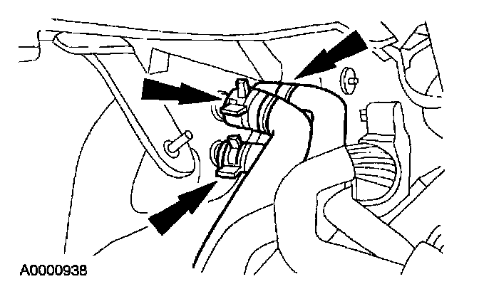
4. Disconnect the heater hose assembly from the heater core.
5. Disconnect the manifold and tube assembly from the thermostatic expansion valve.
6. Remove the instrument panel. For additional information, refer to: Dashboard/Instrument Panel. Service and Repair
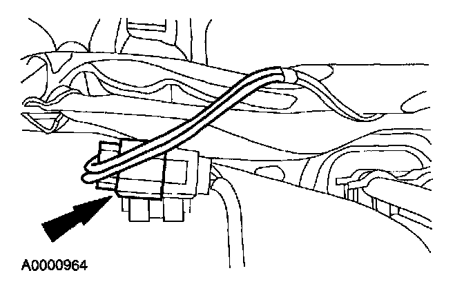
7. Disconnect the connector located on the top of the evaporator core housing.
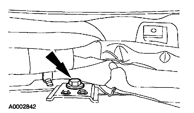
8. Remove the cowl top attachment bolt.
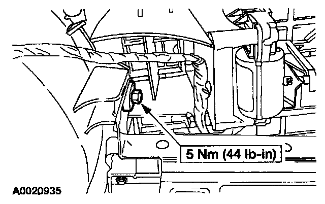
9. Remove the evaporator housing attachment bolt.
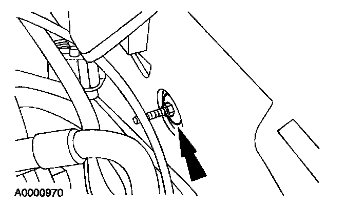
10. Remove the nut and washer assembly retaining the evaporator housing to the bulkhead.
NOTE: Nut and washer assemblies removed in steps 9, 10 and 11 are located in the engine compartment.
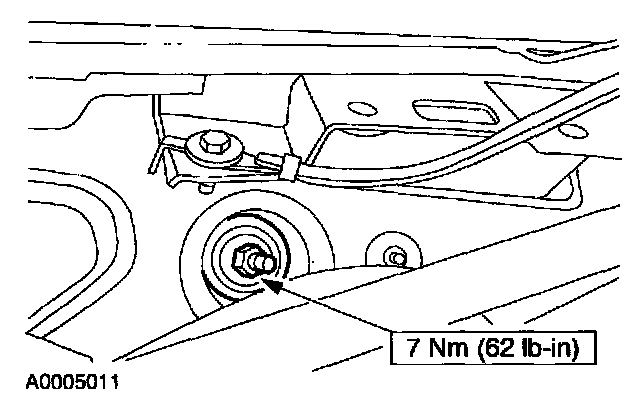
11. Remove the nut and washer assembly retaining the evaporator housing to the bulkhead.
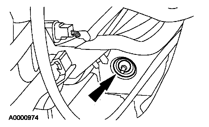
12. Remove the nut and washer assembly retaining the evaporator housing to the bulkhead.
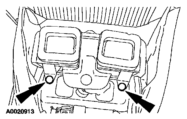
13. Remove two push pins from the rear seat floor ducts.
14. Remove the evaporator core housing.
INSTALLATION
1. Position the evaporator housing.
2. Install the push pins in the rear seat floor ducts.
3. Install the nut and washer assembly.
4. Install the nut and washer assembly.
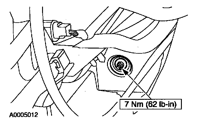
5. Install the nut and washer assembly.
6. Install the evaporator housing attachment bolt.
7. Install the cowl top attachment bolt.
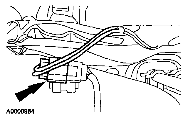
8. Install the connector.
9. Install the instrument panel. Refer to: Body and Frame, Interior Moulding/Trim, Dashboard/Instrument Panel, Service and Repair, Removal and Installation, Removal and Installation
10. Install the thermostatic expansion valve manifold and tube assembly.
11. Install the heater hose assembly at the heater core.
- Make sure that the heater hoses are installed in the correct position.
- Lubricate the coolant hoses with MERPOL(R) meeting Ford specification ESE-M99B144-B or plain water only, if needed.
12. Fill the cooling system.
13. Evacuate and recharge the refrigerant system with R-134a Refrigerant YN-19 or equivalent meeting Ford specification WSH-M17B19-A.
14. Connect the battery ground cable.
- Check for correct hose installation by verifying DATC system operation.