Steering - Steering Column Pop/Click Noise
Article No.02-21-3
STEERING - STEERING COLUMN POP/CLICK NOISE
REPAIR PROCEDURE
10/28/02
FORD:
2002 THUNDERBIRD
LINCOLN:
2001-2002 LS
ISSUE
Some vehicles may exhibit a pop or click type noise from the steering column while turning the steering wheel. This may be caused by a lack of lubrication at the interface of the Upper Tilt Shaft to Upper Tilt Shaft Bearing surface in the steering column.
ACTION
Lubricate the Upper Tilt Shaft to Upper Tilt Shaft Bearing surface area of the steering column using the following service procedure.
SERVICE PROCEDURE
1. Position the steering column so that it is telescoped fully rearward (extended) and the tilt position is in the middle of the travel.
2. Remove the steering wheel. Refer to Workshop Manual, Section 211-04.
3. Remove the two (2) phillips screws on the bottom of the lower steering column shroud. Remove the upper and lower shroud and set aside.
4. Unsecure the clockspring/multi-function switch assembly from the steering column by depressing the 3 clips on the back of the assembly. Pull the assembly off the column and allow it to hang from the wire harness.
5. Use external snap ring pliers to remove the Upper Steering column tilt Shaft snap ring.
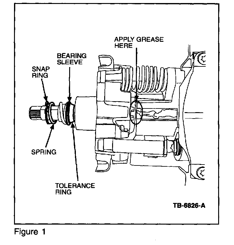
6. Remove the spring and bearing sleeve beneath the snap ring (Figure 1).
7. Using a flat screwdriver, carefully pry the tolerance ring up the shaft and remove.
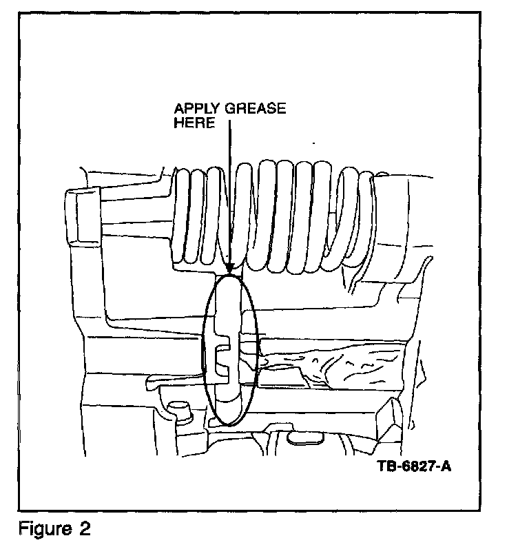
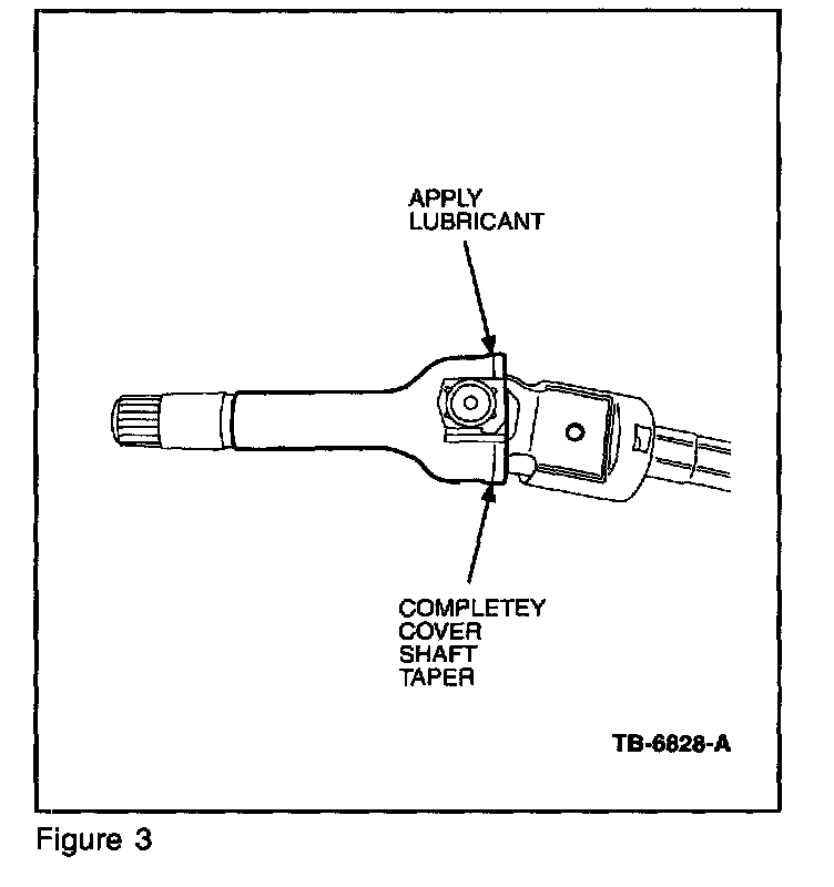
8. Push the shaft forward positioning it so that the tapered surface of the shaft (where it contacts the upper bearing inner race) is clearly visible between the steering column upper bearing housing and inner housing (Figures 2 and 3).
9. Reconnect the battery cable so the power tilt switch is active.
10. Using a small brush apply a generous amount of Multi-purpose Grease, part number XG-4, to the shaft taper. Use the tilt switch to raise the column up, and apply the lubricant all around the bottom and sides of the shaft surface.
11. Lower the column and repeat the application of lubricant to the top and sides of the shaft taper.
NOTE:
MAKE CERTAIN THE LUBRICANT COVERS ENTIRE SURFACE OF THE SHAFT TAPER WHERE IT ENGAGES THE BEARING INNER RACE. REFER TO FIGURE 2.
12. Disconnect the battery.
13. Install the tolerance ring, bearing hat, spring and slide the snap ring on the shaft.
14. Position a large 1/2" drive, deep-well socket over the steering column shaft, which will squarely push the snap ring into place.
15. Install the steering wheel retaining bolt through the drive opening in the socket and tighten until the snap ring seats in the groove on the shaft. Remove the bolt and socket.
16. Install the clockspring/multi-function switch assembly and steering column shroud.
17. Install the steering wheel and a new retaining bolt, part number W705317-S424. Torque bolt to 28 Lb-ft (38 N.m). Refer to Workshop Manual, Section 211-04.
18. Connect the battery and verify repair.
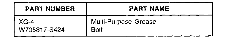
Parts Block
OTHER APPLICABLE ARTICLES: NONE
WARRANTY STATUS: Eligible Under The Provisions Of Bumper To Bumper Warranty Coverage
OPERATION DESCRIPTION TIME
022103A Lubricate The Upper Tilt 1.9 Hrs
Shaft To Upper Tilt Shaft
Bearing Surface Area Of
The Steering Column
DEALER CODING
CONDITION
BASIC PART NO. CODE
3C529 42
OASIS CODES: 303000, 702000, 702300

Disclaimer