Diagnostic Trouble Code Descriptions
Fig. 2 System checker.:
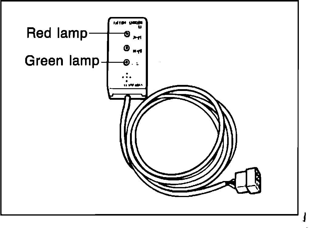
System checker 83 (49 G030 920) Fig. 2 can be used to detect (via the control unit check terminal) and indicate any problems for each sensor and damaged wiring or poor contact or short circuit between each of the sensor-control units. The red lamp on the checker is used for code extraction and the green light is used to verify oxygen sensor operation.
Fig. 3 System codes.:
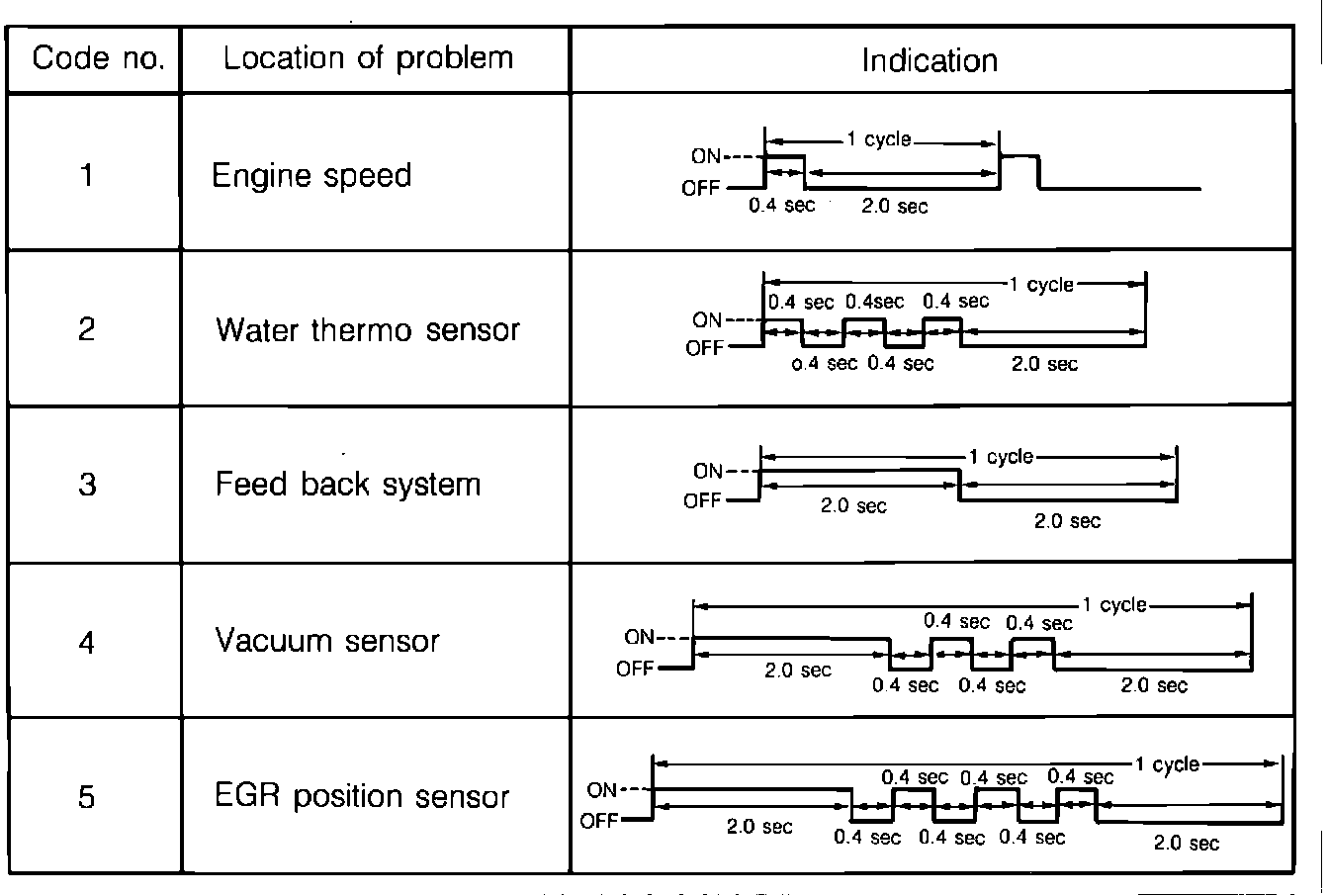
Trouble is indicated by a red light and a buzzer. The indication for problems of each sensor are shown in Fig. 3.
NOTES
1. If there is trouble in 2 or more places, the indication will be for the lower code number first.
2. Even if the problem is corrected during indication, 1 cycle will be indicated.
3. If, after a malfunction has occurred the IG key is switched OFF, the malfunction indicator for the feedback system will not be displayed on the checker.
4. The control unit has a built-in safe mechanism. If a malfunction occurs during driving, the control unit will on its own initiative send out a command, and driving performance will not be affected.
Malfunction:
a. Water thermosensor..... Control unit maintains a constant 80°C (176°F) command.
b. Feedback system......... Control unit holds A/F solenoid to 30% duty, (dwellmeter reading: 18°).
c. Vacuum sensor........... Control unit prevents operation of EGR valve, and holds A/F solenoid to 0% duty
d. EGR position sensor..... Control unit prevents operation of EGR valve.