Venturi Kit Field Installation Procedures (1983 ATX Vehicles Only)
PARTS INFORMATIONVenturi Kit: FE01 23 530
Kit Component Parts:
PART NAME QTY REMARKS
Primary Venturi 1 Not required for Calif. models
Rubber 1 Same as above
Venturi Gasket 1 Same as above
Primary Main Air Bleed 1
Air Horn Gasket 1
Clip (E-shape) 1
Cotter Pin 1
STEP 1 Check the VIN. If it is higher than those listed below do not install the kit. It has been
installed during production.
JM1GC221 D1525016 JM1GC241 D1507209 JM1GC311 D1517185
STEP 2 If the VIN is before those listed above, check for previously-installed Venturi Kit.
STEP 3 Inspecting for previous installation of Venturi Kit.
1) Check for a white paint mark on the carburetor air horn. If white paint mark is present, kit has already been installed.
2) If no white paint mark, remove the primary main air bleed from the primary venturi.
Emulsion Tubes:
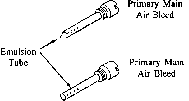
3) Look closely at the emulsion tube. If the emulsion tube is pointed near the end (see illustration at right) the Venturi Kit has already been installed.
If the emulsion tube is flat at the end (see illustration at right) the Venturi Kit has not been installed. Proceed with the installation procedures as follows.
STEP 4 Kit installation procedures.
1) Remove the air cleaner.
Float Level:

2) Check the float level WITH THE ENGINE IDLING.
If the level is not between the center and upper limit of the notch it must be adjusted once the air horn has been removed. (Rememberremove air horn gasket when performing float adjustment.)
3) Disconnect the negative battery cable.
Air Horn Parts:
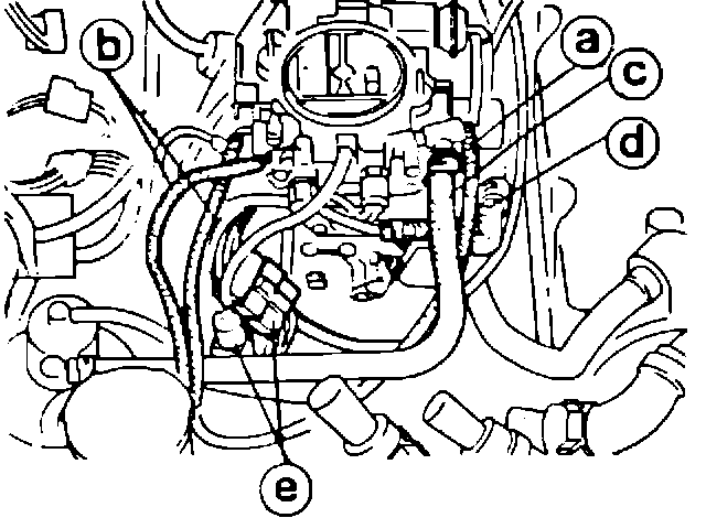
Air Horn Parts:
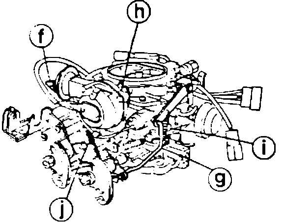
4) Remove the air horn (the following parts must be disconnected or removed).
a. Air hose for high altitude compensator (Federal models only)
b. Air hose for high altitude compensator (Federal models only)
c. Air vent hose
d. Fuel hose
e. Electrical connector
f. Vacuum hose for choke diaphragm
g. Accelerator pump connecting rod
h. Choke rod
i,j. Spring
Primary Venturi Location:
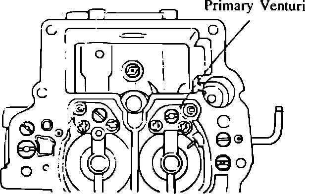
5) FEDERAL & CANADA MODELS
Replace the primary venturi and primary main air bleed with the modified ones.
Primary Venturi Assembly:
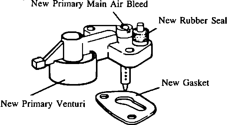
a. Remove and discard the primary venturi together with the primary main air bleed (the gasket between the venturi and the carburetor body must be discarded and adjacent surface must be completely cleaned of gasket residue.
b. Assemble the primary venturi, main air bleed and rubber provided in the kit and install them using the new gasket.
Primary Main Air Bleed Location:
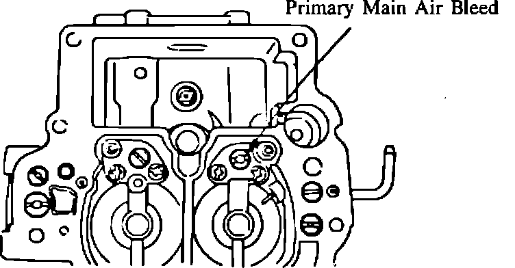
CALIFORNIA MODELS
Replace the primary main air bleed with the modified one provided in the kit.
Note: Replacement of the primary venturi and gasket are not necessary for California models.
"H" Adjustment:
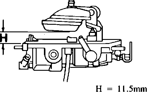
6) Float level adjustment.
a. Position the air horn upside down on a bench and adjust clearance (H) to 11.5 mm by bending tang which contacts needle.
Note: 1. Let the float lower by its own weight and measure the float level WITHOUT AIR HORN GASKET.
2. Measure the LOWEST POINT OF FLOAT.
7) Assemble the carburetor in the reverse order of disassembly. Use the new air horn gasket, clip and cotter pin provided in the kit.
Carburetor Air Horn Location:
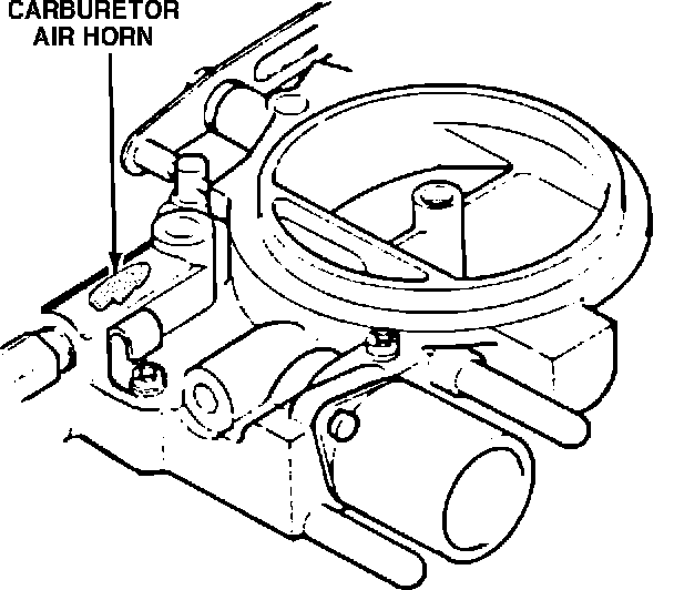
8) Place a white paint mark on the carburetor air hom as shown in the illustration.
9) Install the negative battery cable.
Float Level:
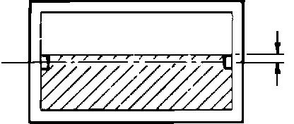
10) Check the float level through the sight glass WITH THE ENGINE IDLING. The float level MUST BE BETWEEN THE CENTER AND UPPER LIMIT OF THE NOTCH. If not, re-adjustment of the float level is necessary.
11) Check all fuel lines and connections for leaks once assembly has been completed.
12) Install the air cleaner.