DTC 03
Fig. 18 Connecting A Dwellmeter To Check Connector:
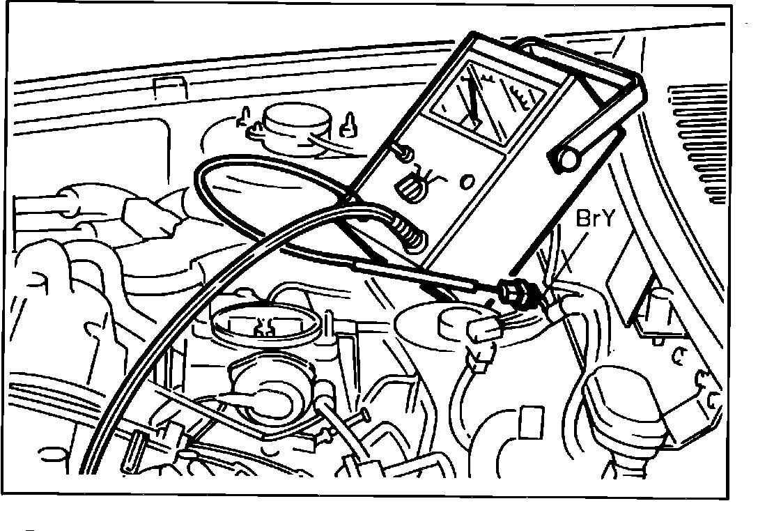
NOTE: Be sure the ignition, spark plugs, carburetor float level, vacuum hose routing etc... are in normal condition. Be sure the air cleaner is installed and idle compensator is closed.
1. Connect a dwellmeter to the BrY wire in the check connector Fig. 18.
2. Set the dwellmeter on the 90°, or 4 cylinder setting.
3. Run the engine at idle and note the reading on the dwellmeter.
4. If the dwellmeter reading is 0° the probable cause is:
Fig. 19 Control Unit Schematic:
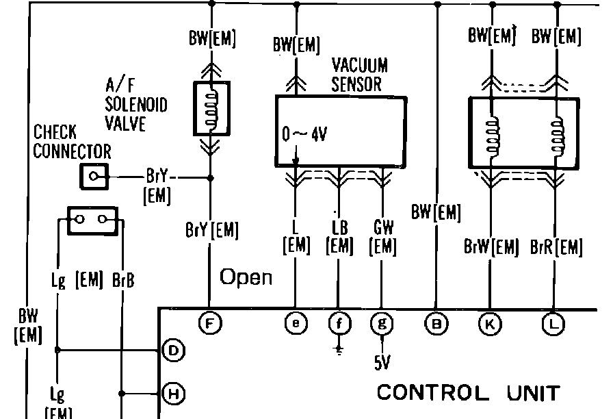
a. Wiring harness from check connector BrY terminal to control unit F terminal is open Fig. 19.
Fig. 20 Open Control Unit Transistor:
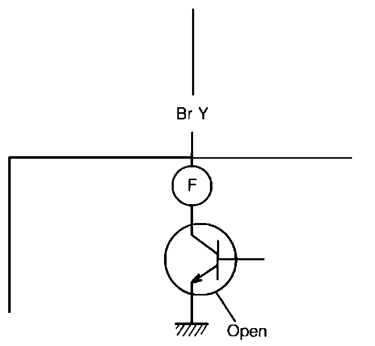
b. Control unit malfunction, open transistor for A/F solenoid Fig. 20.
Fig. 21 Control Unit Schematic:
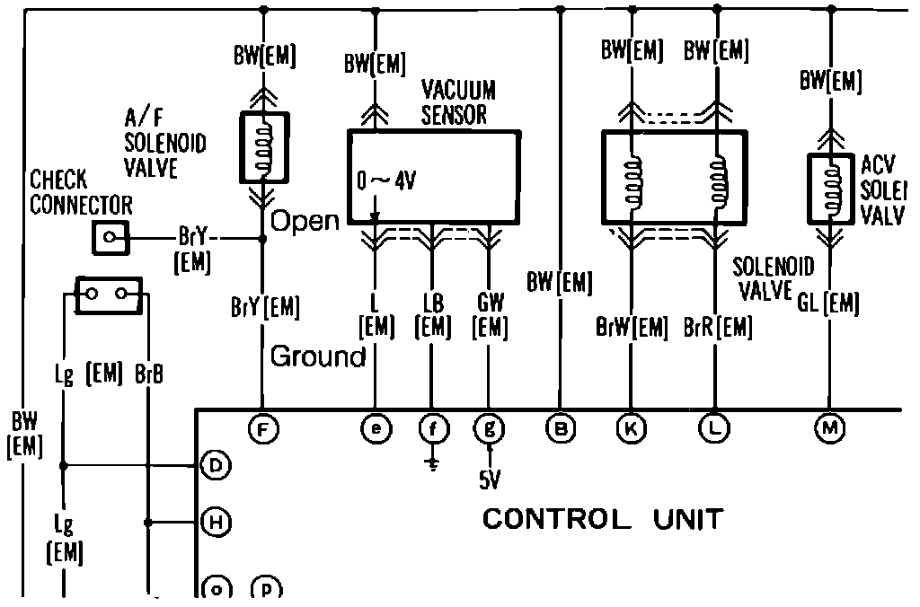
5. If the dwellmeter is 90° check the following:
a. Wiring harness from IG to check connector BrY terminal is open Fig. 21.
b. Wiring harness from check connector BrY terminal to control unit F terminal is grounded.
Fig. 22 Shorted Control Unit Transistor:
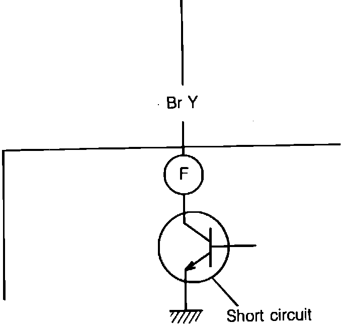
c. Control unit malfunction, shorted transistor for A/F solenoid Fig. 22.
Fig. 2 System checker.:
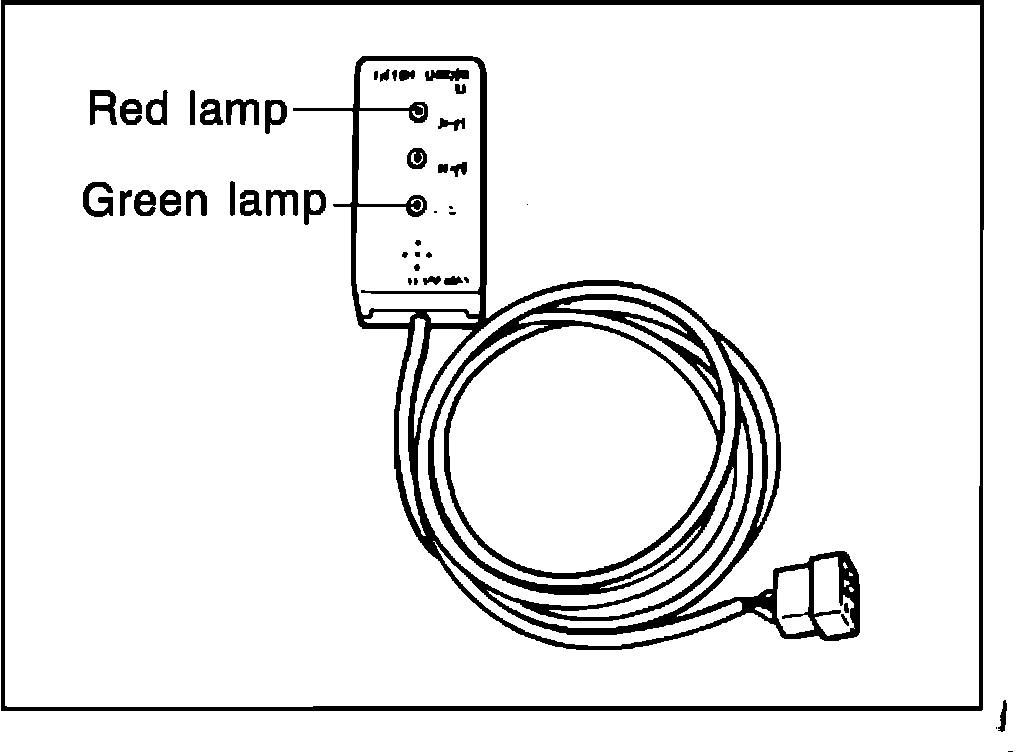
6. If dwellmeter reading is 18° (fixed duty). Check if the green lamp (feedback signal) illuminates or not.
7. If green lamp does not illuminate, air/fuel mixture is lean, check for:
a. Vacuum leak.
a. Air is pulled into exhaust manifold.
a. Incorrect operation of No. 2 ACV.
a. Carburetor jets are clogged.
a. Valve of the A/F solenoid is stuck in the lower position.
Fig. 23 Green Lamp Illuminated, Oxygen Sensor:
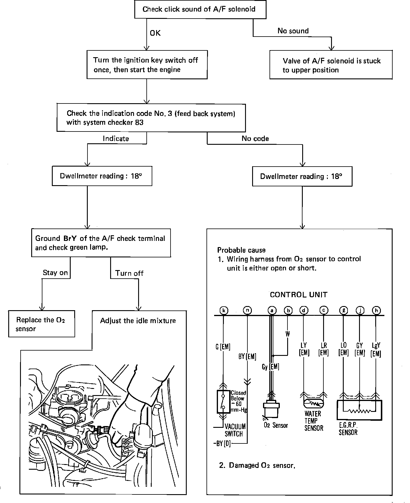
8. If green lamp stays on refer to Fig. 23.