ABS Light: Testing and Inspection
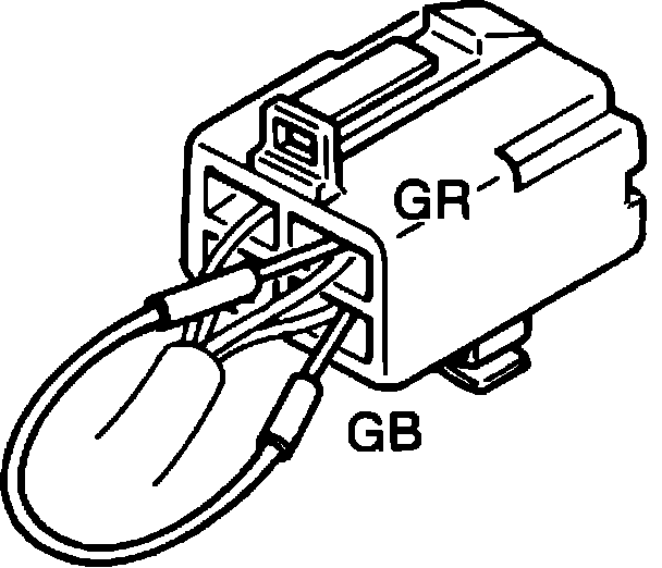
Fig. 3 Check connector terminal identification.:
1988 626 & MX-6
1. Connect terminal wires GR and GB of check connector, Fig. 3, with a jumper wire. The check connector is located forward of the control unit which is under the driver's seat.
2. Turn ignition switch to On position.
3. Ensure warning light is illuminated, then wait 1-2 seconds.
4. Turn ignition switch to Off position, then disconnect jumper wire from terminal GR.
5. Start engine and wait for warning light to go off. One failure memory is erased each time the above steps are taken. If warning light illuminates or blinks after step 5, read and note diagnosis indication. The memory has the capacity for storing 32 failures.
6. Turn ignition switch to Off position.
7. Remove jumper wire.