Circuit
1. Remove rear seat and the control unit cover.2. Disconnect AAS control unit connectors, then turn ignition switch to On position.
3. Check resistance of terminals, Fig. 7, while turning steering wheel, Fig. 8, as shown in test chart, Fig. 9.
Fig. 7 AAS Control Unit Terminals A, C & D:
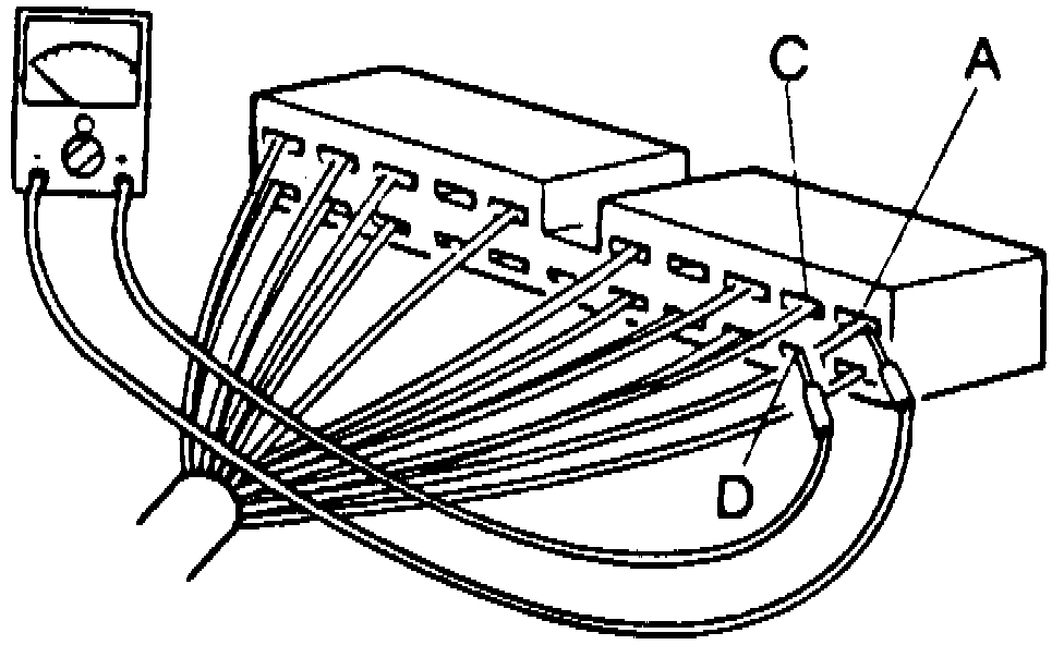
Fig. 8 Steering Wheel Test Positions:
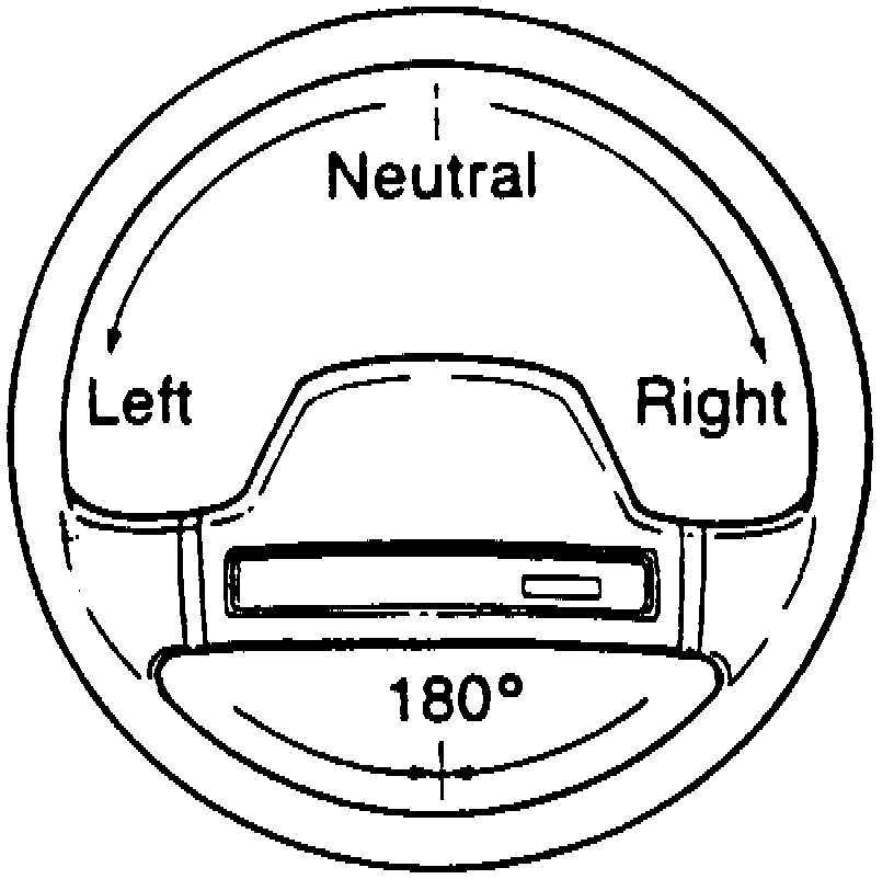
Fig. 9 Angle Sensor Circuit Test Chart:
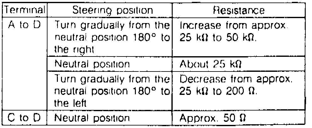
4. If resistances are not as specified, check the angle sensor and wiring harness.