Disassembly and Assembly
STEERING GEAR AND LINKAGE DISASSEMBLY/ASSEMBLY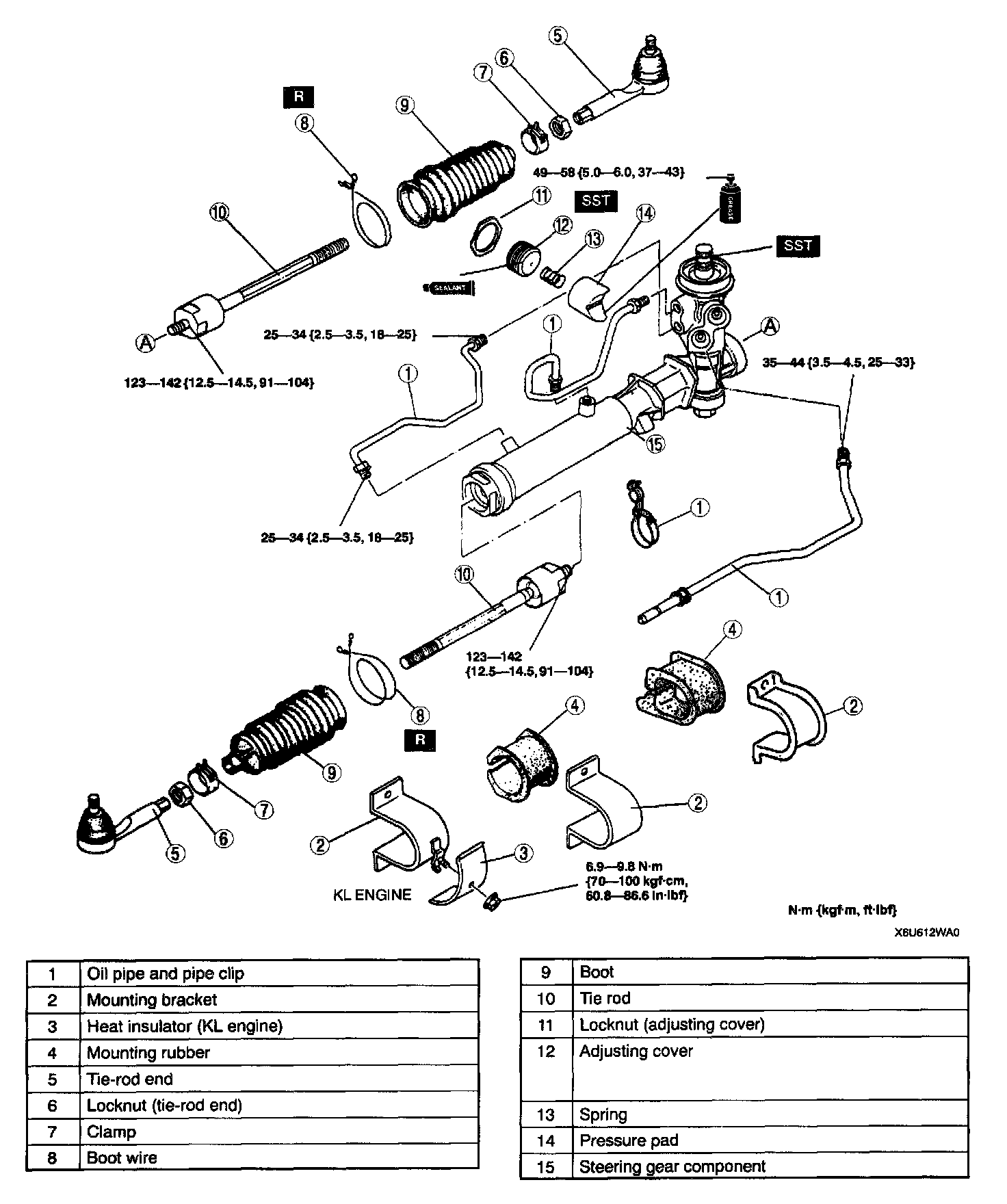
1. Disassemble in the order indicated in the table.
2. Assemble in the reverse order of removal.
ADJUSTING COVER ASSEMBLY NOTE
1. Set the rack in the center position.
2. Tighten the adjusting cover to 9.8 Nm (100 kgf-cm, 87 inch lbs.), then loosen it.
3. Tighten again to 4.4 - 5.4 Nm (45 - 55 kgf-cm, 39 - 48 inch lbs.), and then return it 20 degrees.
4. Apply thread-locking compound to the exposed threads of the adjusting cover.
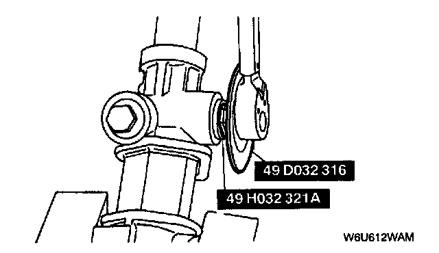
5. Attach the Special Service Tool (SST) and a pull scale to the pinion shaft.
6. Measure the pinion preload.
^ If not within specification, repeat steps 2-6.
Rack position Center ±90°
Pinion preload 1.2 - 1.5 Nm (12 - 16 kgf-cm, 11 - 13 inch lbs.)
Pull scale reading 12 - 15 N (1.2 - 1.6 kgf, 2.8 - 3.3 lbs.)
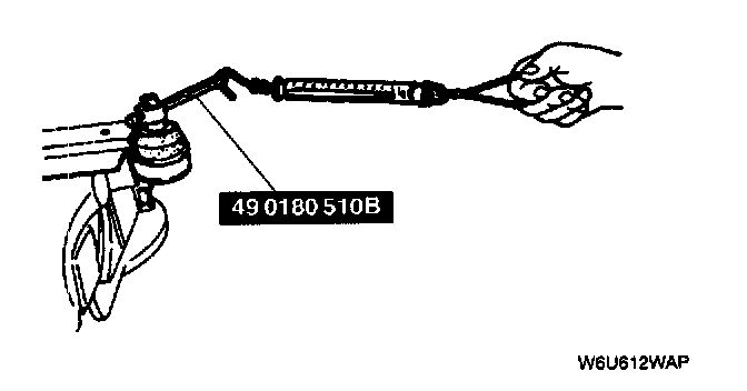
7. Tighten the locknut while holding the adjusting cover by using the SST.
Tightening torque 49 - 58 Nm (5.0 - 6.0 kgf-m, 37 - 43 ft. lbs.)
STEERING GEAR AND LINKAGE INSPECTION
TIE-ROD END INSPECTION
1. Inspect the tie-rod end for damage and boot cracks.
^ Replace it as necessary.
2. Inspect the ball joint for looseness.
^ Replace the tie-rod end as necessary.
3. Rotate the ball joint 5 times.
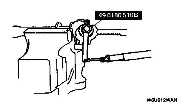
4. Measure the rotation torque of the ball joint by using the SST and a pull scale.
^ If not within specification, replace the tie-rod end.
Rotation torque 0.3 - 2.9 Nm (3 - 30 kgf-cm, 2.6 - 26 inch lbs.)
Pull scale reading 3 - 29 N (0.3 - 3 kgf, 0.7 - 6.6 lbs.)
TIE ROD INSPECTION
1. Inspect the tie rod for bending and damage.
^ Replace it as necessary.
2. Inspect the ball joint for looseness.
^ Replace the tie-rod as necessary.
3. Swing the tie rod 5 times.
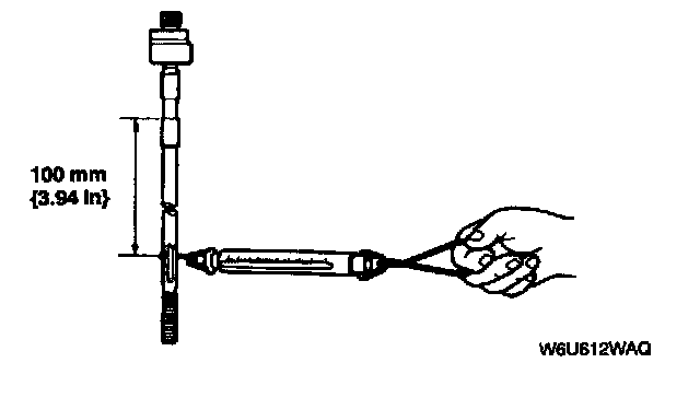
4. Measure the swinging torque by using a pull scale.
^ If not within specification, replace the tie rod.
Swinging torque 0.1 - 3.4 Nm (1 - 35 kgf-cm, 0.9 - 30 inch lbs.)
Pull scale reading 0.7 - 21 N (0.07 - 2.2 kgf, 0.16 - 4.8 lbs.)