Removal and Replacement
AUTOMATIC TRANSAXLE REMOVAL/INSTALLATION [GF4A-EL]1. Disconnect the negative battery cable.
2. Drain the ATF into a container.
Warning: Improperly jacking a transaxle is dangerous. It can slip off the jack and cause serious injury.
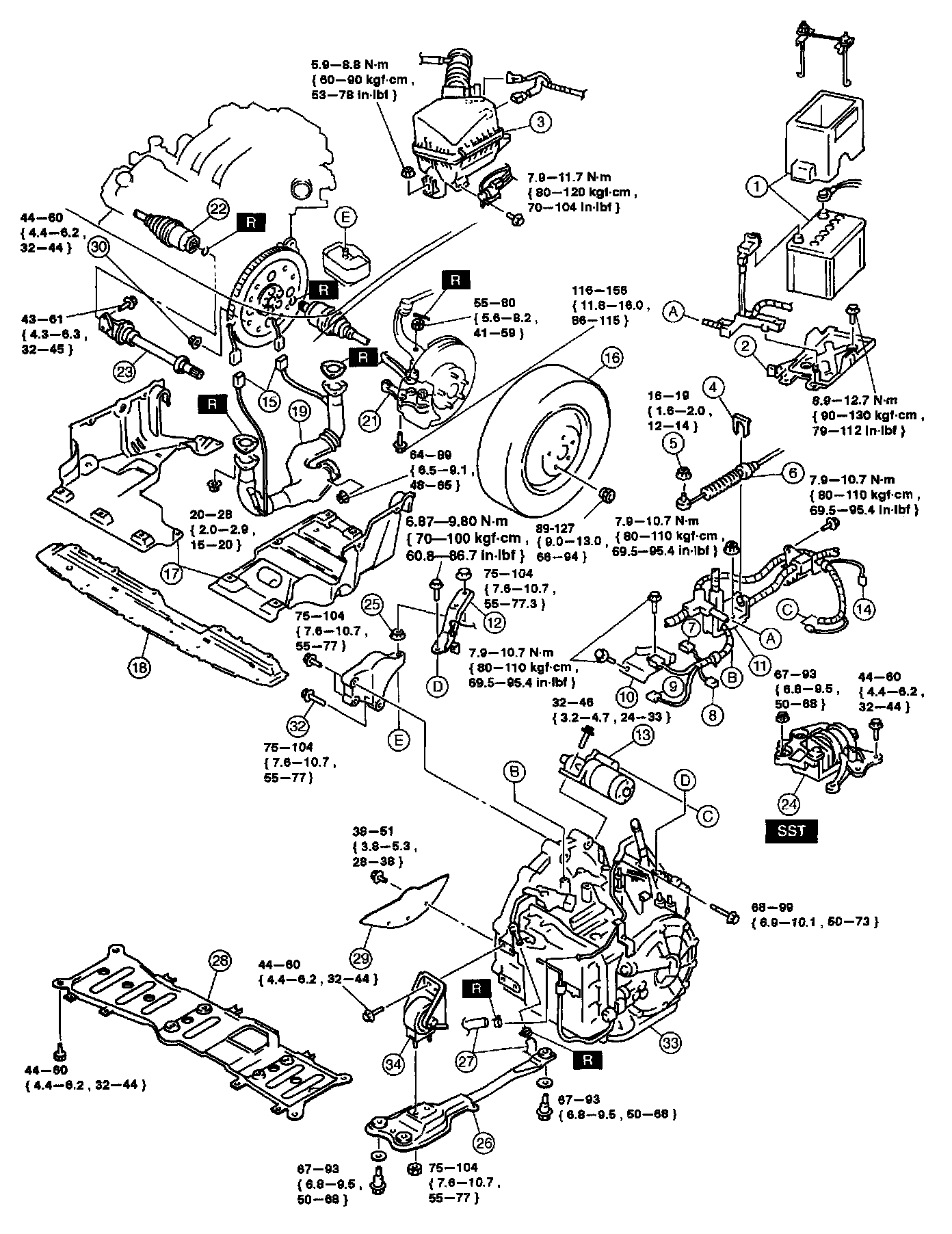
Exploded View

Legend 1

Legend 2
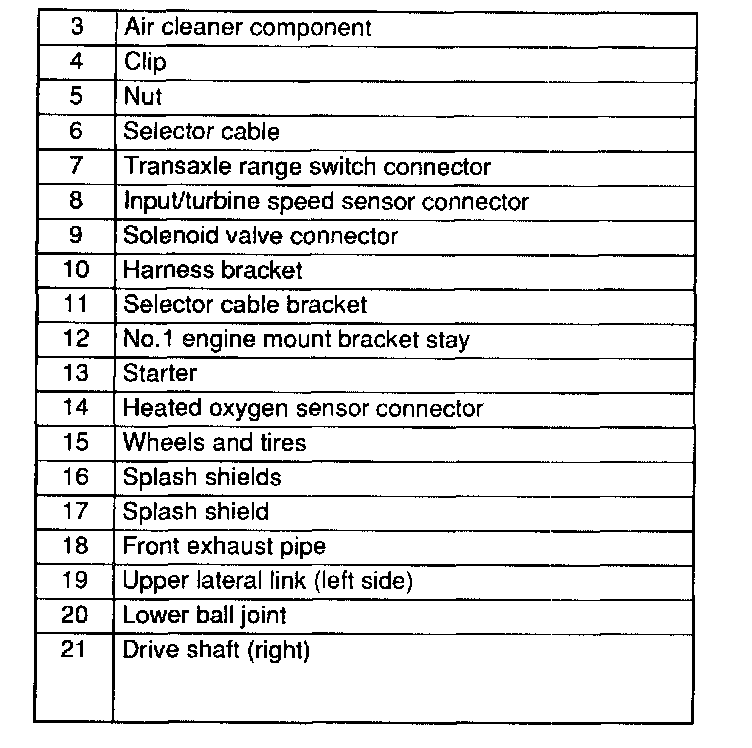
Legend 3 - 21
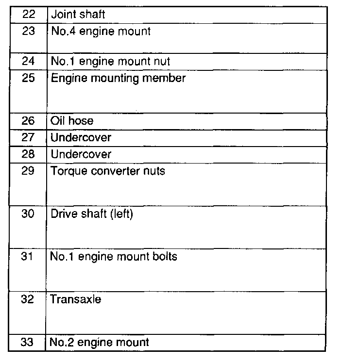
Legend 22 - 33
3. Remove in the order indicated in the table.
4. Install in the reverse order of removal.
5. Fill the transaxle with the specified ATF after installation.
6. Connect the negative battery cable.
7. Inspect the operation of the TR switch.
8. Inspect the operation of the selector lever.
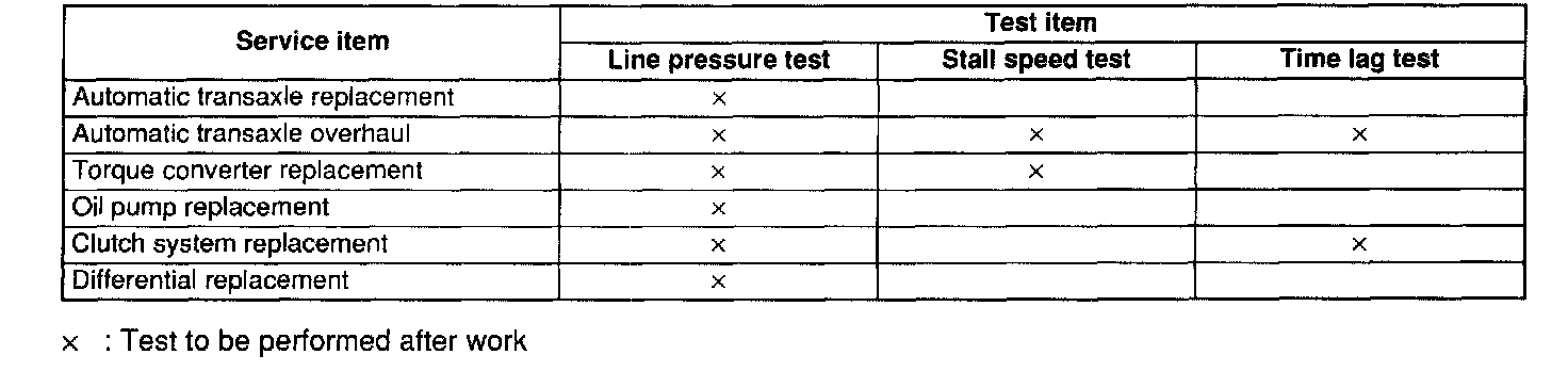
9. Carry out the mechanical system test
10. Carry out the road test.
No.4 Engine Mount Removal Note
1. Support the engine using the SST.
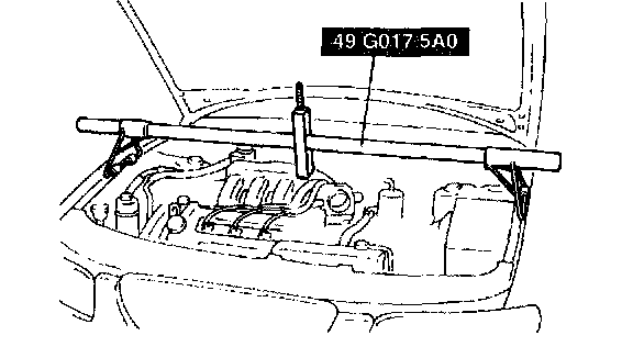
2. Remove the No.4 engine mount.
Torque Converter Nuts Removal Note
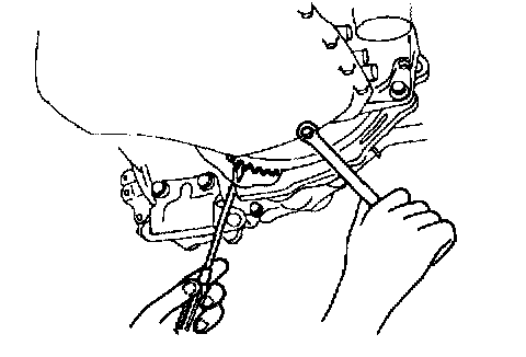
1. Hold the drive plate and remove the torque converter nuts.
Transaxle Removal Note
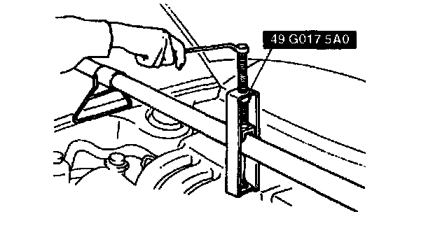
1. Loosen the SST (engine support) and lean the engine toward the transaxle.
2. Support the transaxle on a jack.
Warning: Verify that the transaxle is securely supported by the jack. If the transaxle falls, serious injury or death and damage to the vehicle could result. Before removing the transaxle make sure that the jack is securely supporting it.
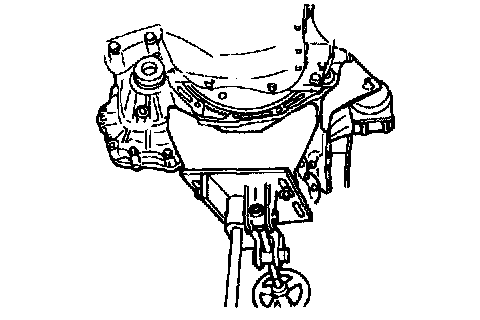
3. Remove the transaxle mounting bolts.
4. Remove the transaxle.
Transaxle Installation Note
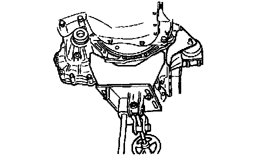
1. Set the transaxle on a jack and lift it into place.
Warning: Verify that the transaxle is securely supported by the jack. If the transaxle should fall, serious injury or death and damage to the vehicle could result. Before removing the transaxle make sure that the jack is securely supporting it.
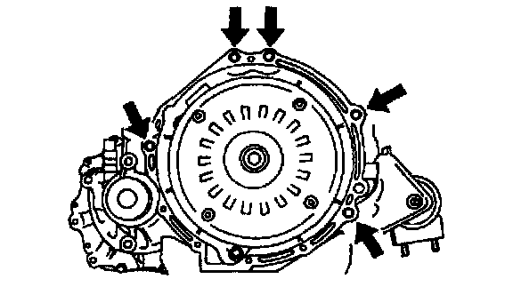
2. Install the transaxle mounting bolts.
Tightening torque 68 - 99 Nm (6.9 - 10.1 kgf-m, 50 - 73 ft. lbs.)
3. Install the torque converter nuts.
Tightening torque 38 - 60 Nm (3.8 - 6.2 kgf-m, 28 - 44 ft. lbs.)
4. Hand-tighten the No.4 engine mount nuts.
No.1 Engine Mount Bolts Installation Note
Caution: Align the transaxle bolt holes and the engine mount exactly. Any misalignment can result in bolts and bolt holes becoming damaged or stripped during installation.
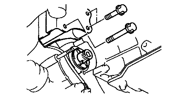
1. Use the SST (engine support) to make sure the transaxle bolt holes and No. 1 engine mount align.
2. Tighten the bolts to the specified torque.
Tightening torque 75 - 104 Nm (7.6 - 10.7 kgf-m, 55 - 77 ft. lbs.)
Engine Mounting Member Installation Note
1. Install the engine mounting member and No.2 engine mount, making sure that the No.2 engine mount stud bolt passes through the No.2 engine mount bracket installation hole.
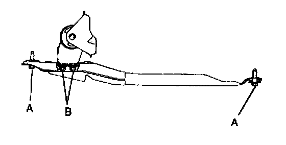
2. Install bolts A as shown.
Tightening torque A: 67 - 93 Nm (6.8 - 9.5 kgf-m, 50 - 68 ft. lbs.)
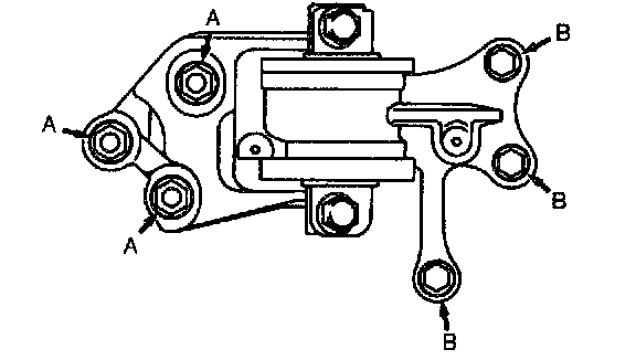
3. Tighten nut B as shown.
Tightening torque B: 75 - 104 Nm (7.6 - 10.7 kgf-m, 55 - 77 ft. lbs.)
4. Tighten the No.4 engine mount nuts.
Tightening torque
A: 67 - 93 Nm (6.8 - 9.5 kgf-m, 50 - 68 ft. lbs.)
B: 44 - 60 Nm (4.4 - 6.2 kgf-m, 32 - 44 ft. lbs.)
5. Remove the SST (engine support).