Diagnostic Connector - ABS: Testing and Inspection
ABS HYDRAULIC UNIT (HU)/CONTROL MODULE (CM) INSPECTION1. Disconnect the negative battery cable.
2. Connect the SST between the ABS HU/CM and harness connector with the ignition switch off.
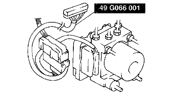
3. Attach the tester leads to the SST and inspect voltage referring the table.
Terminal Voltage Table (Reference)
(Engine is idling, and connector is connected unless otherwise indicated)
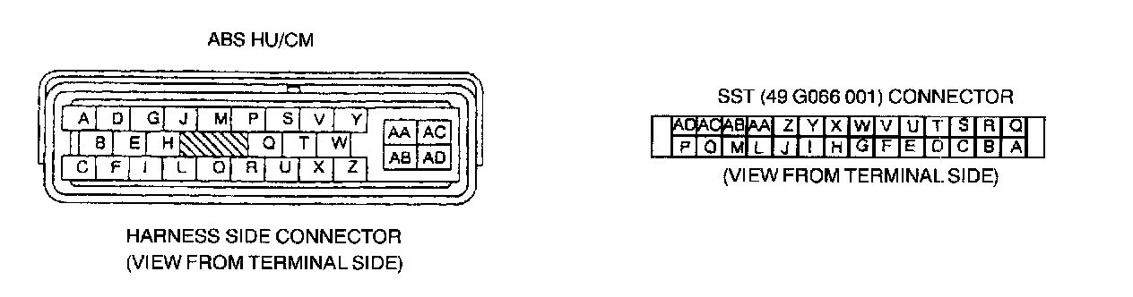
1 of 2
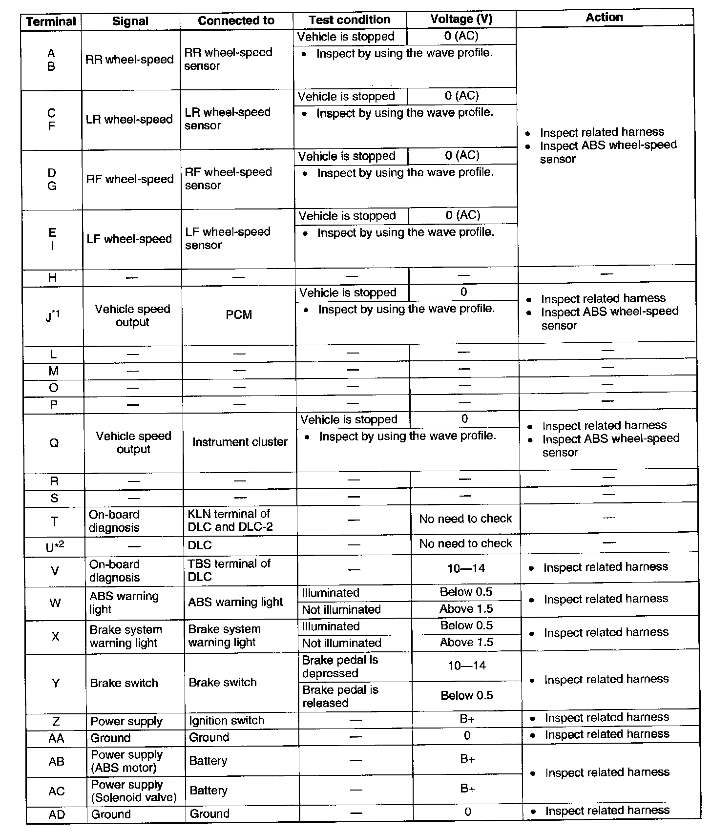
2 of 2
*1: ATX only
*2: Use this terminal at factory only, not used for inspection and repair at field
Inspection Using An Oscilloscope (Reference)
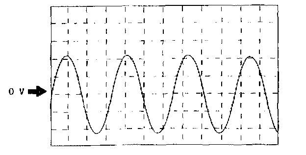
Wheel speed
^ ABS HU/CM terminal:
RR: A (+) - B (-)
LR: C (+) - F (-)
RF: D (+) - G (-)
EF: E (+) - I (-)
^ Oscilloscope setting: 1 V/DIV (Y), 2 ms/DIV (X), AC range
^ Vehicle condition: Driving 30 km/h (18.6 mph)
Note:
^ As vehicle speed increases, period of wave shortens.
^ If there is malfunctioning in the sensor rotor, wave profile warps.
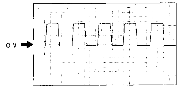
Vehicle speed output (to PCM) (ATX only)
^ ABS HU/CM terminal: J (+) - AA (-)
^ Oscilloscope setting: 1 V/DIV (Y), 5 ms/DIV (X), DC range
^ Vehicle condition: Driving 30 km/h (18.6 mph)
Note:
^ As vehicle speed increases, period of wave shortens.
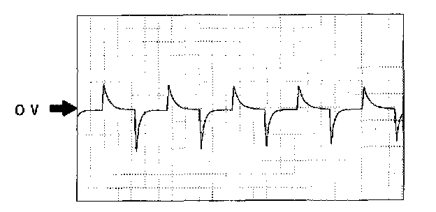
Vehicle speed output (to instrument cluster)
^ ABS HU/CM terminal: Q (+) - AA (-)
^ Oscilloscope setting: 1 V/DIV (Y), 5 ms/DIV (X), DC range
^ Vehicle condition: Driving 30 km/h (18.6 mph)
Note:
^ As vehicle speed increases, period of wave shortens.