Evaporator Case: Service and Repair
COOLING UNIT REMOVAL/INSTALLATION1. Discharge the refrigerant from the system. (See REFRIGERANT CHARGING.)
2. Disconnect the negative battery cable.
3. Remove the glove compartment.
4. Disconnect cooler pipe No.1 and No.2. (See Refrigerant Lines Removal Note.) (See Refrigerant Lines Installation Note.)
CAUTION: If moisture or foreign material enters the refrigeration cycle, cooling ability will be lowered and abnormal noise will occur. Always immediately plug all open fittings after removing any refrigeration cycle parts to keep moisture or foreign material out of the cycle.
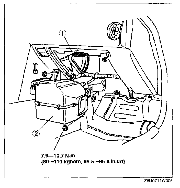
5. Remove in the order indicated below. Do not allow compressor oil to spill.
1. Seal plate
2. Cooling unit.
See Cooling Unit Installation Note
6. Install in the reverse order of removal.
7. Perform refrigerant system performance test. (See REFRIGERANT SYSTEM PERFORMANCE TEST.)
Cooling Unit Installation Note
1. When installing a new cooling unit, add DENSO OIL9 compressor oil into the refrigeration cycle.
Supplemental amount (approximate quantity) 40 ml {40 cc, 1.4 fl oz}
COOLING UNIT DISASSEMBLY/ASSEMBLY
CAUTION: If moisture of foreign material enters the refrigeration cycle, cooling ability will be lowered and abnormal noise will occur. Always immediately plug all open fittings after removing any refrigeration cycle parts to keep moisture or foreign material out of the cycle.
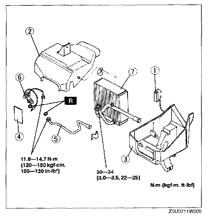
1. Disassemble in the order indicated below.
1. Thermoswitch
2. See Thermoswitch Assembly Note
3. Case (top)
4. Case (bottom)
5. Tar patty
6. Pipe
7. Expansion valve
8. See Expansion Valve Assembly Note
9. Evaporator
10. See Evaporator Assembly Note
2. Assemble in the reverse order of disassembly.
Evaporator Assembly Note
1. When installing a new evaporator, add DENSO OIL9 compressor oil into the refrigeration cycle.
Supplemental amount (approximate quantity) 40 ml (40 cc, 1.4 fl oz}
Expansion Valve Assembly Note
1. Apply compressor oil to the O-rings and connect the joints.
2. Install the heat-sensing tube to its proper position.
Thermoswitch Assembly Note
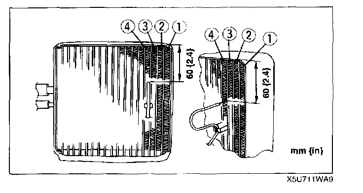
1. Insert the thermoswitch probe in location as shown in the figure.