Flex Plate: Service and Repair
CRANKSHAFT, FLYWHEEL AND DRIVE PLATE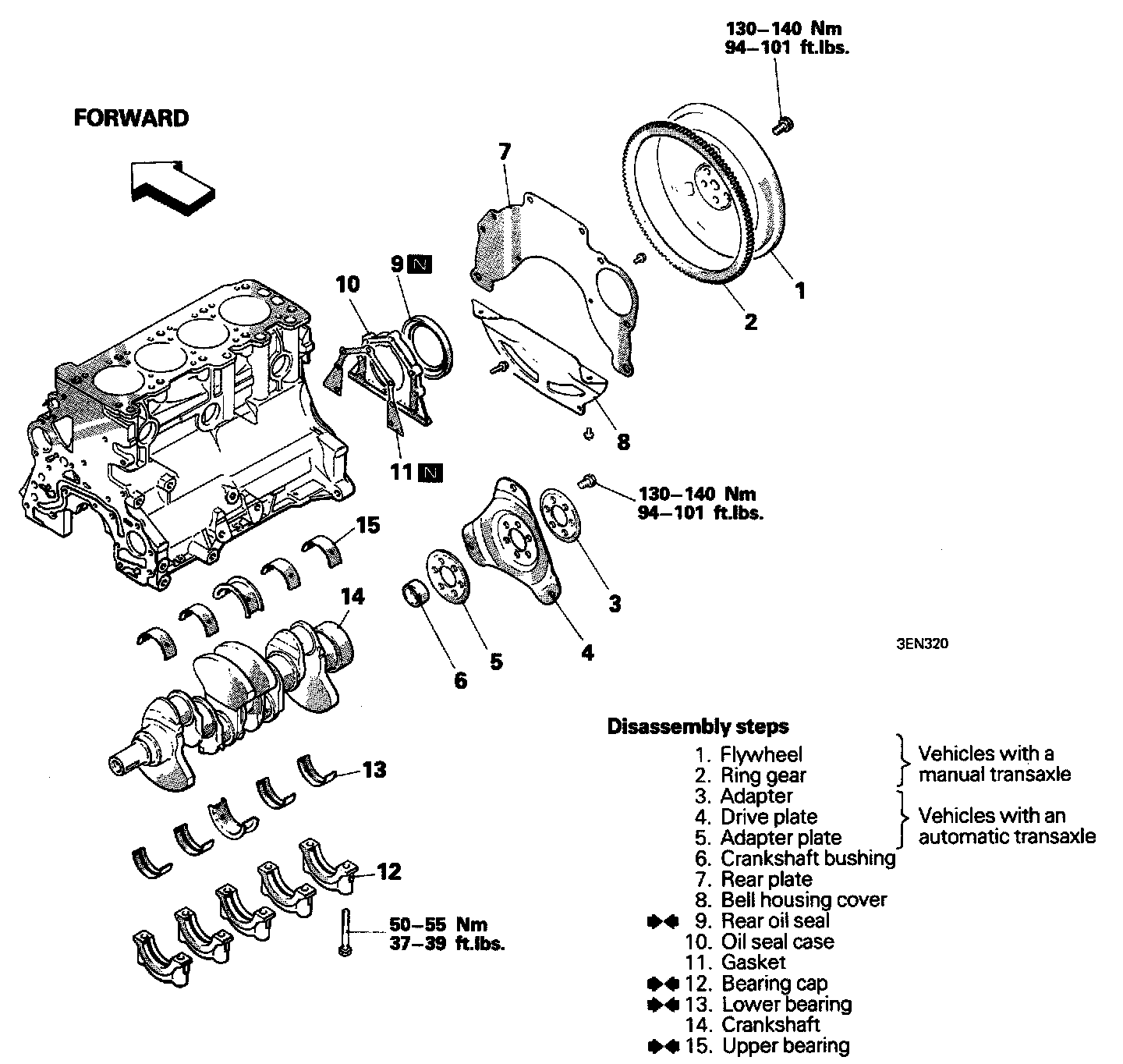
DISASSEMBLY AND REASSEMBLY
INSPECTION
CRANKSHAFT
(1) Check the crankshaft journals and pins for damage, uneven wear and cracks. Also check oil holes for clogging. Correct or replace any faulty part.
(2) Inspect out-of-round and taper of crankshaft journal and pin.
Standard dimension:
Crankshaft journal O.D. 57 mm (2.24 in.)
Crank pin 0.0. 45 mm (1.77 in.)
Crankshaft journal pin out-of-round and taper
Less than 0.015 mm (.0006 in.)
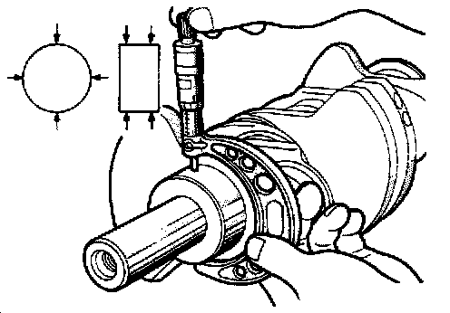
MAIN BEARINGS AND CONNECTING ROD BEARINGS
Visually inspect each bearing for peeling, melt, seizure and improper contact. Replace the faulty bearings.
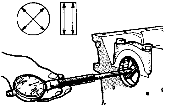
OIL CLEARANCE MEASUREMENT
To check the oil clearance, measure the outside diameter of crankshaft journal and crank pin and the inside diameter of bearing. The clearance can be obtained by calculating the difference between the measured outside and inside diameters.
Oil clearance:
Crankshaft main bearing
0.02-0.05 mm (.0008- .0019 in.)
Connecting rod bearing
0.02-0.05 mm (.0008- .0019 in.)
Limit:
Crankshaft main bearing
0.1 mm (.004 in.)
Connecting rod bearing
0.1 mm (.004 in.)
PLASTIC-GAUGE METHOD
Plastic-Gauge may be used to measure the clearance.
(1) Remove oil and grease and any other dirt from bearings and journals.
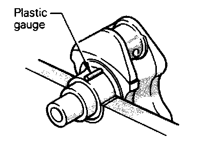
(2) Cut Plastic-Gauge to the same length as the width of the bearing and place it in parallel with the journal, off oil holes.
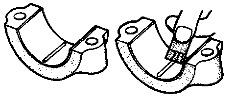
(3) Install the crankshaft, bearings and caps and tighten them to the specified torques. During this operation, do NOT turn the crankshaft. Remove the caps. Measure the width of the Plastic-Gauge at the widest part by using a scale printed on the Plastic-Gauge sleeve.
If the clearance exceeds the limit, the bearing should be replaced or an undersize bearing used.
When installing a new crankshaft, be sure to use standard size bearings.
Should the standard clearance not be obtained even after bearing replacement, the journal should be ground to undersize and a bearing of the same size should be installed.
OIL SEAL
Check front and rear oil seals for damage or worn lips. Replace any seat that is faulty.
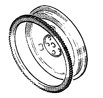
RING GEAR (Vehicles with a manual transaxle)
Check the ring gear for worn, damaged or broken teeth.
Replace the ring gear if teeth are faulty, and also check the starter motor pinion.
Ring Gear Replacement Procedure
(1) Strike outer circumference of ring gear at several points.
CAUTION The ring gear cannot be removed if it is heated.
(2) Install the ring gear on flywheel after heating the ring gear to 260-280°C (500-536°F) for shrink fit.
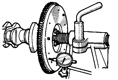
FLYWHEEL (Engine with a manual transaxle)
(1) Visually check the clutch disc friction surface of flywheel for ridge wear, streaks and seizure. Replace as necessary.
(2) If the flywheel runout exceeds the limit, replace it.
Limit: 0.13 mm (.0051 in.)
DRIVE PLATE (Engine with an automatic transaxle)
Replace if deformed, damaged or cracked.
SERVICE POINTS OF REASSEMBLY
15. INSTALLATION OF UPPER BEARING
When reusing the main bearings, install them in their original positions by referring to location marking made at the time of removal.
Be sure that oil holes in bearings align with those in cylinder block.
13. INSTALLATION OF LOWER BEARING
Make sure that a bearing without oil groove is used as lower bearing.
12. INSTALLATION OF BEARING CAP
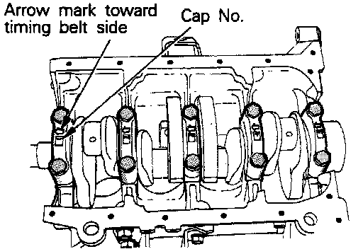
(1) Install the bearing caps with their arrow mark directed toward the timing belt side of engine. Cap numbers must be in correct order.
(2) Tighten cap bolts in the sequence of center, No.2, No.4, front and rear cap bolts.
(3) Cap bolts should be tightened evenly in 2 to 3 steps before they are finally tightened.
(4) Make certain that the crankshaft turns freely and has a proper end play by checking the clearance between center main bearing thrust flange and connecting rod big end bearing.
Crankshaft end play:
0.05-0.18 mm (.0020-.0071 in.)
Limit: 0.25 mm (.0098 in.)
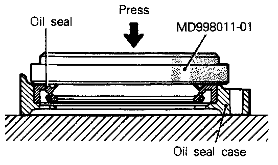
9. INSTALLATION OF REAR OIL SEAL
Install oil seal in the crankshaft rear oil seal case. Using the special tool, press fit the oil seal all the way in without tilting it.