Air Injection Pump: Description and Operation
Fig. 4 - Air Injection Pump:
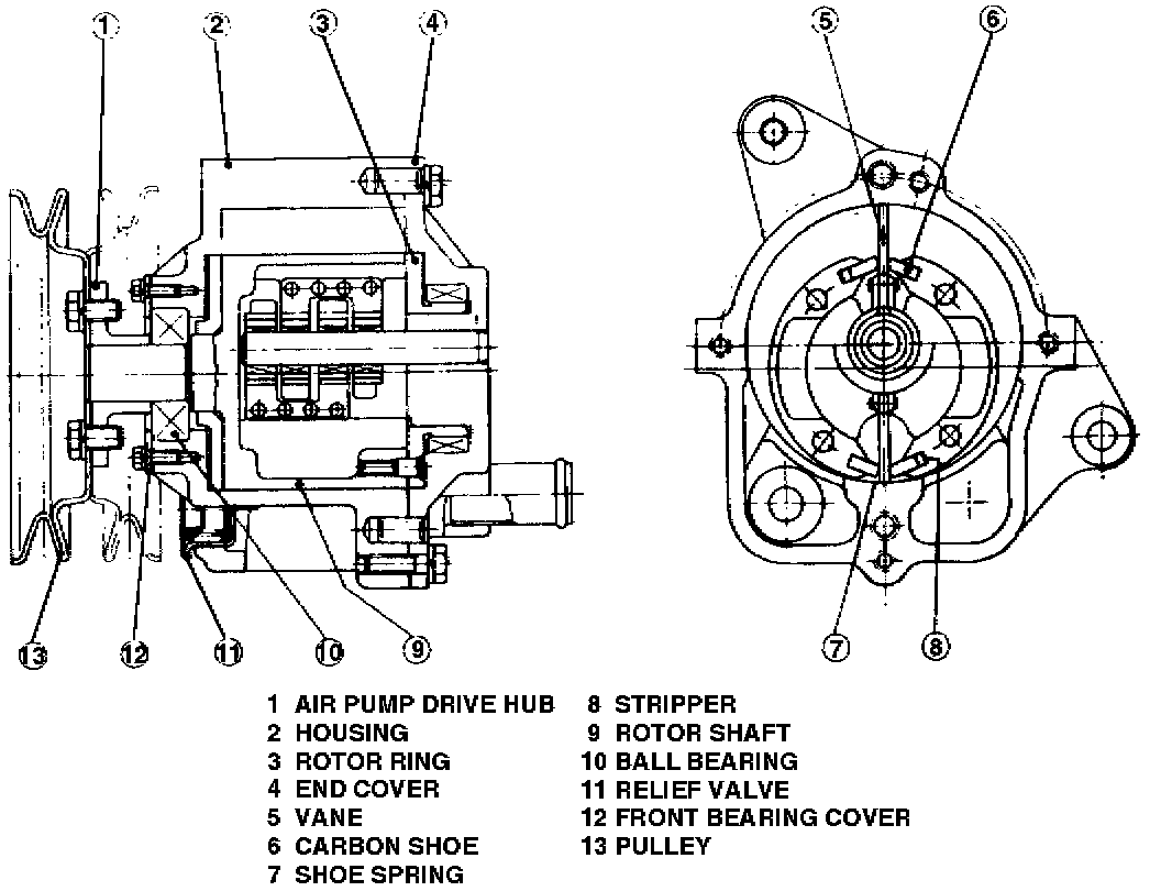
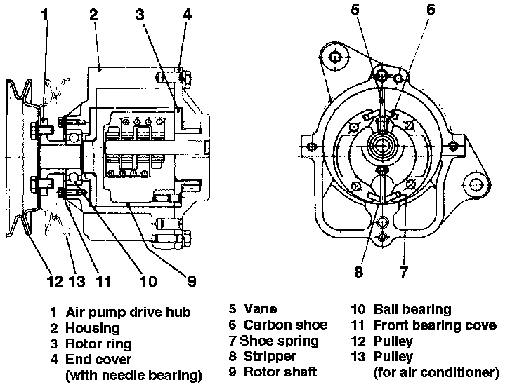
Fig. 5 - Air Injection Pump:
Types of Air Pumps
A positive displacement vane-type air pump requiring no lubrication is used.
- all models--Figs 4 & 5--two vane pump
Air Pump Construction
The belt driven, die-cast aluminum, air pump is attached by brackets to the front of the engine.
Visible Pump Components
- Rotor shaft, drive hub, inlet and outlet tubes.
Pump Rotating Unit
- Composed of rotor, vanes, carbon shoes, and shoe springs.
Pump Operation
The vanes rotate freely--around the off-center pivot pin--following the circular-shaped pump bore.
- In the two-vane type, the vanes form two chambers in the housing.
- Each vane completes a pumping cycle every rotor revolution.
- Air drawn into the inlet cavity--through a tube connected to the air pump air cleaner--is sealed between the vanes and moved into a smaller cavity (the compression area).
- After compression, a vane passes the outlet cavity.
- Subsequently it passes the stripper and a section of the housing that separates the outlet and inlet cavities and again reaches the inlet cavity to repeat the pumping cycle.
The relief valve--consisting of a preloaded spring, seat, and pressure-setting plug and located in the outlet cavity--relieves the outlet air flow when the pressure exceeds a preset value.
- Carbon shoes ride in slots in the rotor designed to permit the shoes to slide and seal the rotor interior from the air cavities.
- Leaf springs behind the leading-side of the shoes beginning in 1975 or behind the follower side of the shoes prior to 1975, compensate for shoe abrasion.
- The steel rotor ring--bolted to the rotor end--positions the rotor and holds the carbon shoes.
- he vane uses needle bearings. All bearings have been greased.
- There are two types of bearing which support the rotor. Ball bearing is used for the front one and the needle bearing is used for the rear.