Code B122
PANEL DIMMING SWITCH POT CIRCUIT
Circuit Description:
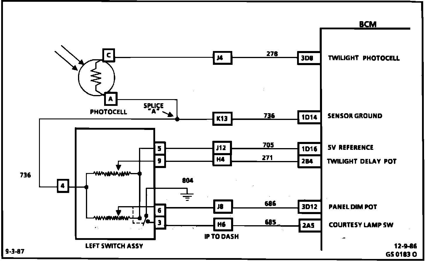
The panel dimmer uses a potentiometer to control the signal voltage to the BCM. The BCM supplies voltage on CKT 705 to the resistor in the left switch assembly and a ground on CKT 736. The wiper provides the voltage signal to the BCM on CKT 686 indicating position of the slider and dim level. When the slider is moved toward the max. position (bright), the voltage signal at BCM terminal 3D12 decreases. As the slider is moved toward the min. position (dim) the voltage signal at the BCM increases. BD42 displays a low % for dim and a high % for bright panel illumination. Code B 122 will set if the ignition is "ON" and the signal voltage indicates less than 2% (high voltage) or over 98% (low voltage). During the time the failure is present a substitute dimming value will be implemented to allow continued operation of interior lighting. The reading from the potentiometer, BD42 however, will display the actual reading.
Test Description: The following numbered steps correspond with the step numbers on the diagnostic chart.
CODE B122PANEL DIMMING SWITCH POT CIRCUIT:
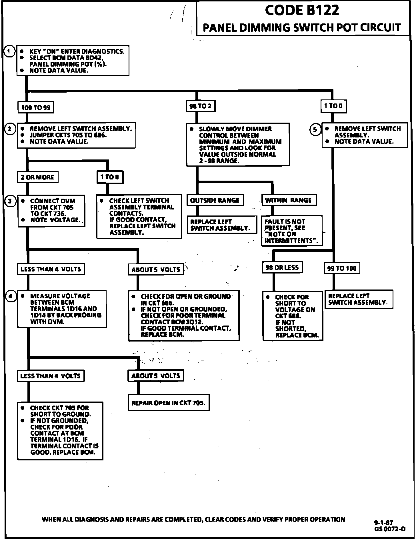
1. BCM data value displays the amount of panel dimming. The normal range is from 2 to 98%.
2. If the open or grounded circuit reading changes to a short to voltage reading after jumpering the switch assembly terminals, the BCM and wiring are OK.
3. Measuring voltage between CKT 705 (5 volts) and CKT 736 determines if 5 volt reference is available at the switch.
4. This step determines if 5 volt reference is available at BCM terminal 1D16.
5. If a short to voltage reading changes to an open circuit reading after disconnecting the switch assembly, the BCM and wiring are OK.
Note On Intermittents
If an intermittent Code B122 is being set, manipulate the related wiring while observing BCM data parameter BD42. If the failure is induced, the reading will jump from its normal value to a reading outside the range of 2 to 98%.