PCV Heater: Testing and Inspection
Chart C-13:
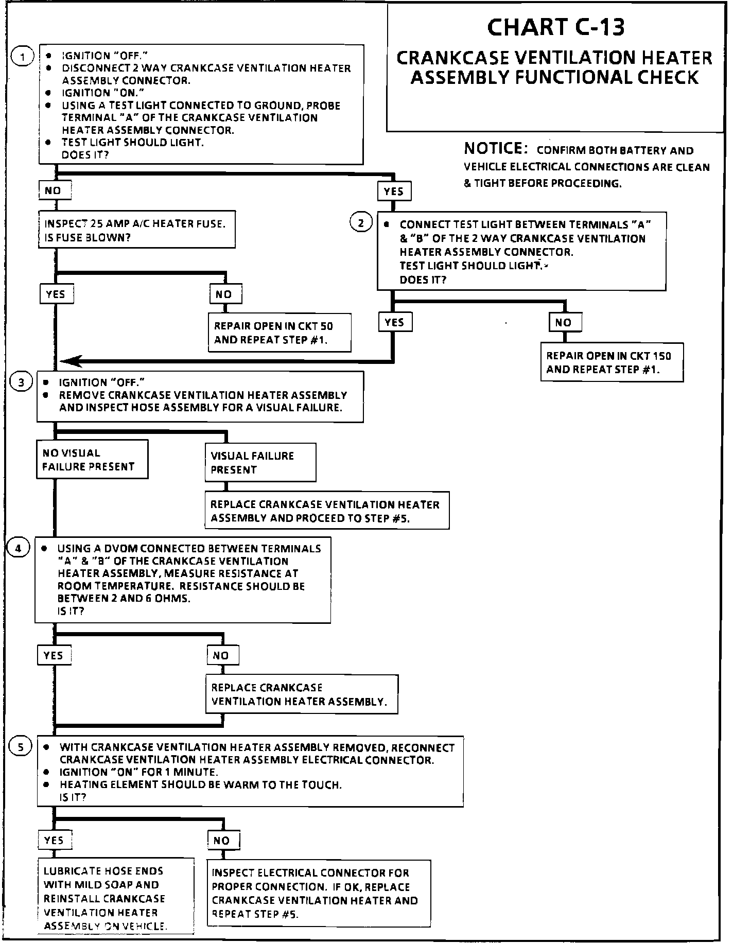
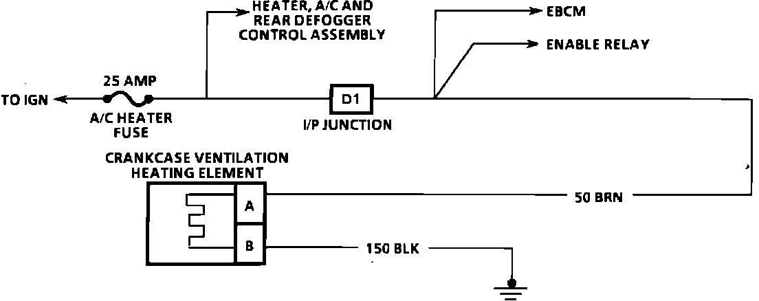
Chart C-13 Wiring Diagram:
***UPDATED BY TSB # 92-6-43 DATED APRIL 1992
Circuit Description:
The crankcase ventilation heater assembly is used to prevent icing in the crankcase ventilation system. The heating element inside the vent hose is used to prevent icing from the oil/air separator to the intake manifold.
The heating element consists of two parallel wires that extend the length of the vent hose. One wire supplies the current when the ignition is turned "ON" while the second wire provides a constant path to ground.
Although the wires are not physically attached, the material between the two wires is conductive. Current is passed through the material between the wires. As the material is heated, electrical resistance increases and current flow decreases. When the material is cooled, electrical resistance decreases, current flow and heat output increases.
By this means, the temperature of the heating element is controlled to maintain approximately 115°F.
Test Description:Number(s) below refer to circled number(s) on the diagnostic chart.
1. This step verifies voltage is present to the crankcase ventilation heater assembly system.
2. This step insures a good path to ground in CKT 150.
3. This step identifies a visual failure.
4. This step identifies an open, or out of range crankcase ventilation heater element.
5. This confirms that the crankcase ventilation heating element is operational and is functioning properly.
Diagnostic Aids:
Check to insure that both battery and associated vehicle electrical connections are clean & tight.