P0650
Circuit Description
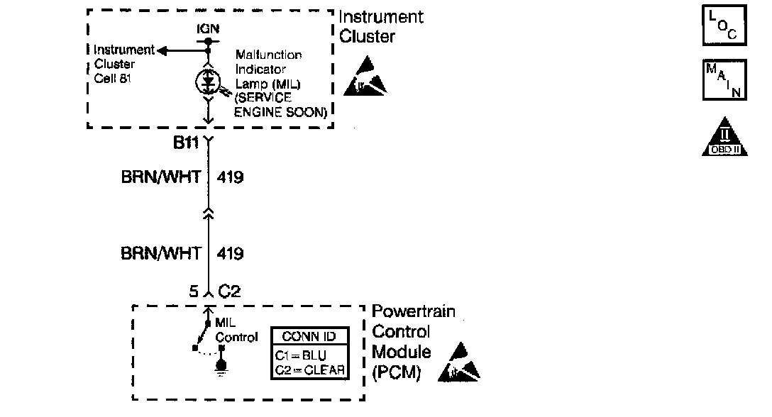
A voltage is supplied directly to the Malfunction Indicator Lamp (MIL). The powertrain control module (PCM) controls the lamp by grounding the control circuit via an internal switch called a driver. The primary function of the driver is to supply the ground for the component being controlled. Each driver has a fault line which is monitored by the PCM. When the PCM is commanding a component ON, the voltage of the control circuit should be near 0 volts. When the PCM is commanding the control circuit to a component OFF, the voltage potential of the circuit should be near battery voltage. If the fault detection circuit senses a voltage other than what is expected, the fault line status will change causing the DTC to set.
Circuit Description
Ignition voltage is supplied directly to the Malfunction Indicator Lamp. The PCM controls the lamp by grounding the control circuit via an internal switch called a driver. The primary function of the driver is to supply the ground for the component being controlled. Each driver has a fault line which is monitored by the PCM. When the PCM is commanding a component on, the voltage of the control circuit should be low (near 0 volts). When the PCM is commanding the control circuit to a component off, the voltage potential of the circuit should be high (near battery voltage). If the fault detection circuit senses a voltage other than what is expected, the fault line status will change causing the DTC to set.
Conditions for Running the DTC
The ignition is on.
Conditions for Setting the DTC
^ An improper voltage level has been detected on the MIL control circuit.
^ The above condition present for at least 30 seconds.
Action Taken When the DTC Sets
^ The PCM will illuminate the Malfunction Indicator Lamp (MIL) during the first trip in which the diagnostic runs and fails.
^ If equipped with traction control, the PCM will command the EBTCM via the serial data circuit to turn OFF traction control and illuminate the TRACTION OFF lamp.
^ The PCM will store conditions which were present when the DTC set as Freeze Frame and Fail Records data.
Conditions for Clearing the MIL/DTC
^ The PCM will turn the MIL OFF during the third consecutive trip in which the diagnostic has been run and passed.
^ The history DTC will clear after 40 consecutive warm-up cycles have occurred without a malfunction.
^ The DTC can be cleared by using the scan tool.
Diagnostic Aids
Check for the following conditions:
^ If the ignition feed circuit is suspected of being open, check if other bulbs on that circuit illuminate.
^ Poor connection at the PCM. Inspect the harness connectors for backed out terminals, improper mating, broken locks, improperly formed or damaged terminals, and poor terminal to wire connection. Refer to Intermittents and Poor Connections Diagnosis.
^ Damaged harness. Inspect the wiring harness for damage. If the harness appears to be OK, disconnect the PCM, turn the ignition on and observe voltmeter connected to the MIL circuit at the PCM harness connector while moving connectors and wiring harnesses related to the MIL control circuit. A change in voltage will indicate the location of the fault. Refer to Intermittents and Poor Connections Diagnosis. Refer to Wiring Repairs in Diagram. Symptom Related Diagnostic Procedures
Test Description
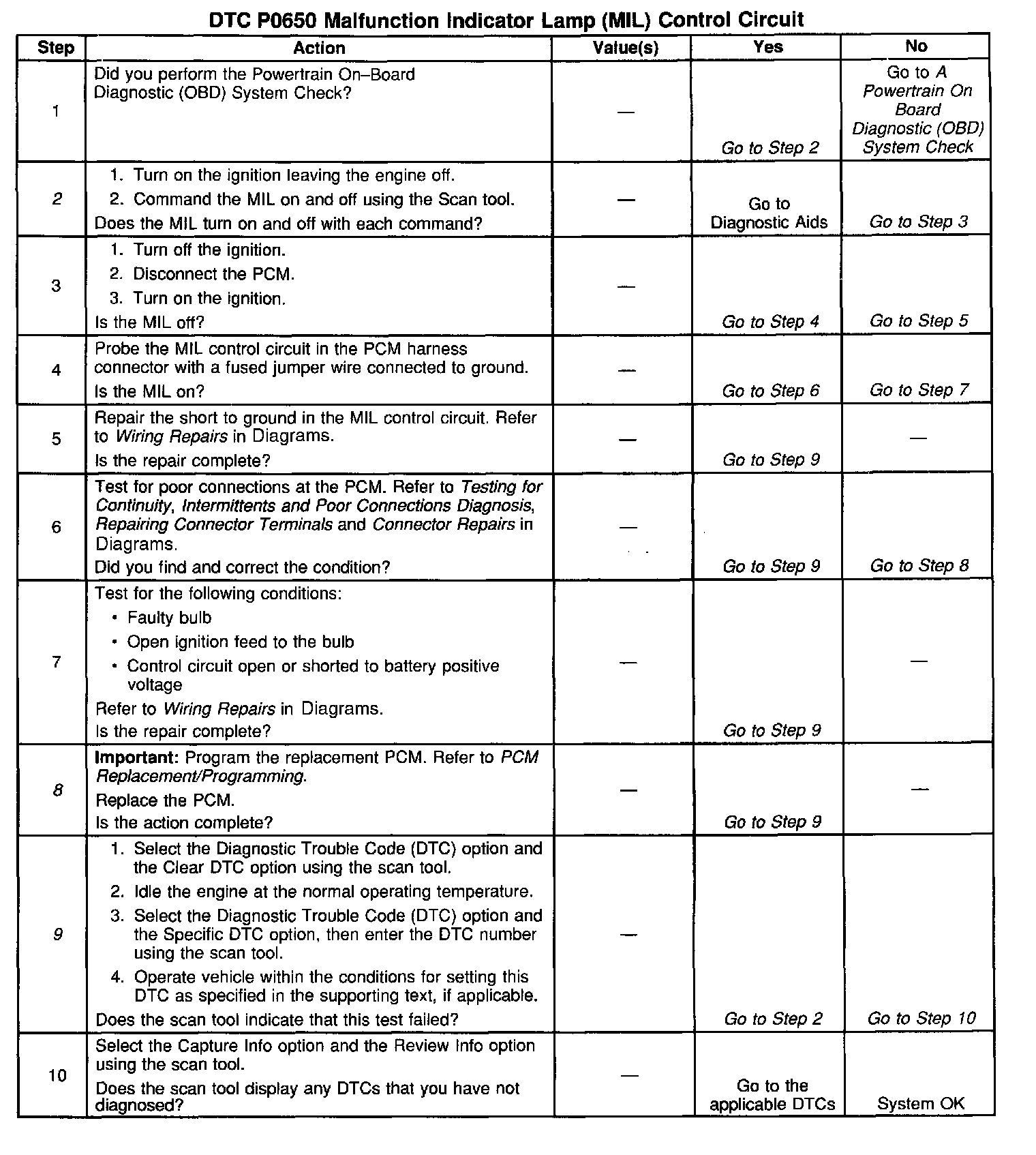
The numbers below refer to the step numbers on the diagnostic table:
Important: If the I/P is completely inoperative, refer to Instrument Panel, Gauges and Warning Indicators.
2. Command both the on and the off states. Repeat the commands as necessary.
8. If you do not find trouble in the control circuit or the connection at the PCM, the PCM may be faulty. However, this is an extremely unlikely failure.
9. This DTC will not report a pass. The scan tool status for this DTC will never report a pass. The scan tool will only display when the diagnostic fails. The repair is not complete if the scan tool indicates that the diagnostic ran and failed.