Brake Pedal Assy: Service and Repair
Brake Pedal Bracket ReplacementRemoval Procedure
1. Remove the IP carrier assembly, to gain access to the brake pedal assembly to cowl mounting bolts.
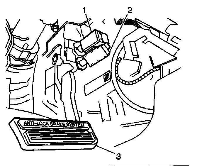
2. Disconnect the electrical connectors from the stoplamp/ABS/shift lock switch (2).
3. Remove the stoplamp/ABS/shift lock switch from the brake pedal assembly.
4. Remove the TCC/cruise control release switch from the brake pedal assembly.
5. Remove the vacuum brake booster pushrod retainer.
6. Remove the pushrod foam spacer.
7. Remove the vacuum brake booster pushrod from the brake pedal.
8. Remove the accelerator control cable.
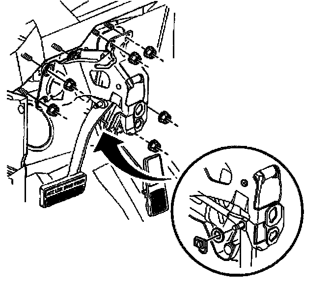
9. Remove the brake pedal assembly to cowl mounting nuts.
10. Remove the brake pedal assembly to booster stud mounting nuts.
11. Remove the brake pedal bracket and pedal assembly.
Installation Procedure
1. Install the brake pedal assembly onto the booster studs.
Notice: Refer to Fastener Notice in Service Precautions.
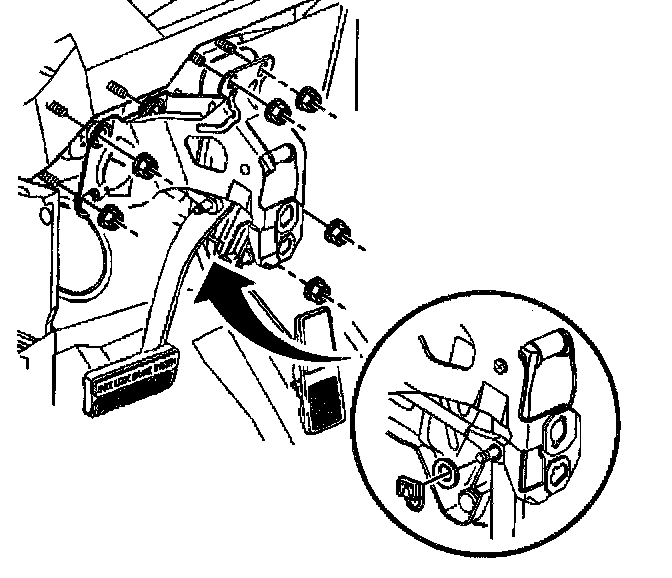
2. Install the booster stud mounting nuts.
Tighten the brake pedal to booster stud mounting nuts to 23 Nm (17 ft. lbs.).
3. Install the brake pedal to cowl studs mounting nuts.
Tighten the brake pedal to cowl studs mounting nuts to 16 Nm (12 ft. lbs.).
4. Apply lubricant, GM P/N 1050109 or equivalent, to brake pedal clevis pin.
5. Install the pushrod onto brake pedal clevis pin.
6. Install the brake pedal foam spacer to the brake pedal clevis pin.
7. Install the pushrod retainer to the brake pedal clevis pin.
8. Install the accelerator control cable.
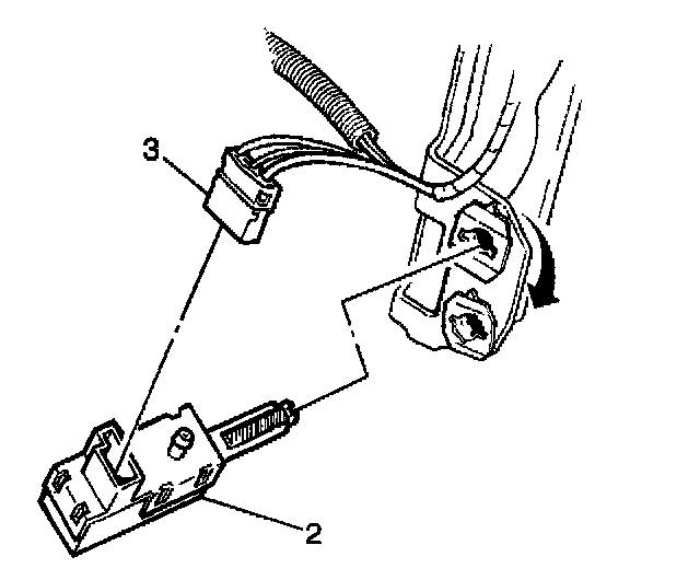
9. Install the electrical connectors to the stoplamp/ABS/shift lock switch (2).
10. Install the stoplamp/ABS/shift lock switch (2).
11. Install the TCC/cruise control release switch.
12. Install the IP assembly.