Lateral Runout Check
Measuring Rotor Lateral Runout:
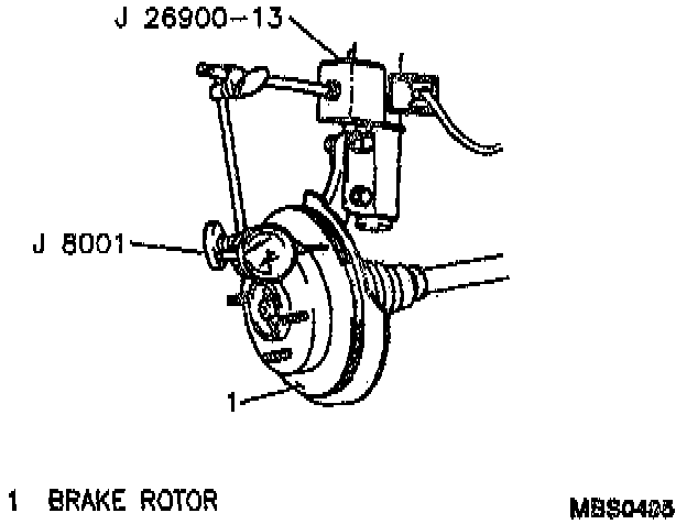
^Tools Required:
- J 8001 Dial Indicator Set
- J 26900-13 Magnetic Base
1. Raise and suitably support vehicle.
2. Remove tire and wheel assembly.
3. Remove caliper. Refer to Caliper.
4. Fasten a J 26900-13 and a J 8001 to the strut so that the indicator button contacts the brake rotor about 10 mm (0.39 inch) from the rotor edge.
5. Zero the J 8001.
6. Move the rotor one complete revolution and observe the total indicated runout.
^ Rotor Lateral Runout (Maximum): 0.10 mm (0.004 inch)
NOTE:
^ If lateral runout exceeds specifications, clean wheel hub and rotor mating surfaces and measure again.
^ If lateral runout still exceeds specifications, index the rotor on the hub one or two bolt positions from the original position.
^ If the lateral runout cannot be corrected by indexing the rotor, check the hub and bearing assembly for excessive play. If hub and bearing assembly are within specifications, refer to Brake Rotor Tolerance and Surface Finish. Rotor Tolerance and Surface Finish
^ A rotor that does not meet the lateral runout specification should be refinished or replaced as necessary.