Hydraulic Modulator-Replacement
Hydraulic Modulator/Motor Pack Assembly:
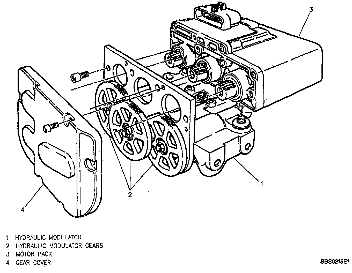
Remove or Disconnect
1. Four Torx head screws and both solenoids from hydraulic modulator/motor pack assembly.
2. Six Torx head screws and gear cover from hydraulic modulator/motor pack assembly.
3. Four Torx head screws and motor pack from hydraulic modulator.
CAUTION
^ Use care when handling motor pack to ensure motor pack connector is not damaged, or accidental intrusion of brake fluid into the motor pack does not occur. This may result in a premature failure of the motor pack.
^ Take care in handling the motor pack. If dropped or damaged during handling, the motor pack must be replaced.
Proportioning Valve:
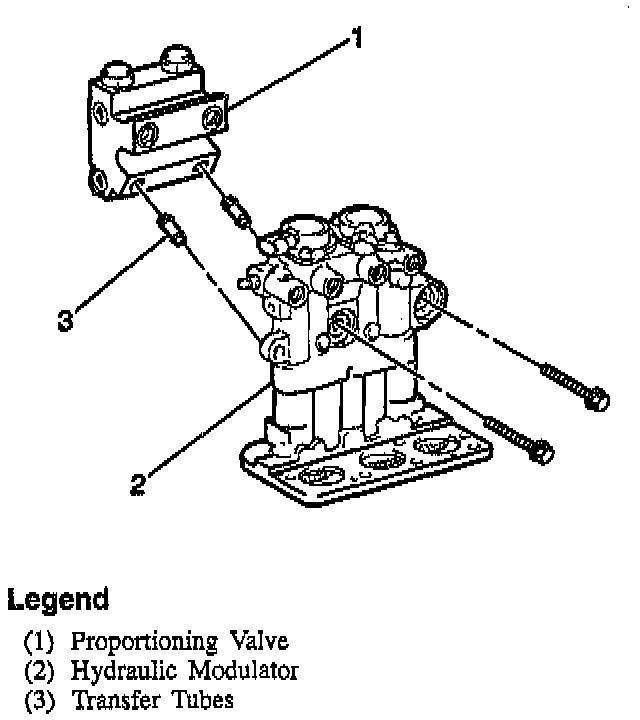
4. Two banjo bolts and proportioning valve from hydraulic modulator.
5. Two transfer tubes with O-rings from proportioning valve or hydraulic modulator.
6. Banjo bolt O-rings front proportioning valve and hydraulic modulator.
CAUTION
^ If the hydraulic modulator is to be replaced, install the three gears in the same location on the replacement modulator. Refer to Gear Replacement earlier in this section.
^ No repair of the hydraulic modulator is authorized. Replace as an assembly.
^ Use new transfer tubes when assembling the proportioning valve to the hydraulic modulator.
^ Make sure two new O-rings are properly installed on each transfer tube.
Install or Connect
1. Two transfer tubes.
2. Lubricate transfer tube O-rings with clean brake fluid.
3. Install transfer tubes to the ports in the hydraulic modulator. Push in by hand to seat tubes.
4. Lubricate new banjo bolt O-rings with clean brake fluid and install into hydraulic modulator and proportioning valve.
5. Proportioning valve to hydraulic modulator. Hold hydraulic modulator and rock into position on proportioning valve, inserting transfer tubes into proportioning valve ports.
6. Two banjo bolts securing proportioning valve to hydraulic modulator.
^ Tighten Banjo bolts to 24 Nm (17 ft. lbs.).
7. With the hydraulic modulator upside down, and the gears facing you, rotate each gear counterclockwise until movement stops. This procedure will position the pistons very close to the top of the hydraulic modulator bore, simplifying the brake bleeding procedure.
8. Motor pack to hydraulic modulator, aligning the three motor pack gears with the modulator gears.
NOTE: Take care in handling the motor pack. If dropped or damaged during handling, the motor pack must be replaced.
9. Four Torx head screws securing motor pack.
^ Tighten Motor pack Torx head screws to 5 Nm (44 inch lbs.).
10. Gear cover to hydraulic modulator/motor pack assembly secure with six Torx head screws.
^ Tighten Gear cover Torx head screws to 4 Nm (36 inch lbs.).
11. Solenoids to hydraulic modulator/motor pack assembly.
A. Lubricate solenoid seals with clean brake fluid.
B. Verify that the solenoid seal is properly positioned to each solenoid.
C. Position solenoids so that their electrical connectors will face the same direction prior to removal.
D. By hand, press down firmly on the solenoids until their flanges seat onto the hydraulic modulator.
12. Four Torx head bolts securing solenoids.
^ Tighten ABS Solenoid Torx head bolts to 5 Nm (44 inch lbs.).