Shift Interlock Solenoid: Service and Repair
REMOVAL PROCEDURE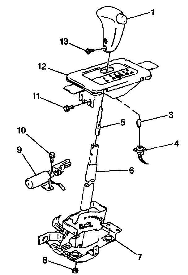
1. Disconnect the negative (-) battery cable.
CAUTION: Refer to Battery Disconnect Caution in Service Precautions.
2. Remove 2 screws and the selector knob (1) from the selector lever (6).
3. Remove 4 screws and the console from the vehicle.
4. Remove 4 screws, the upper cover and the slide cover from the selector lever.
5. Remove the lower cover from the selector lever.
6. Remove the shift lock solenoid (9) electrical connector under the carpet.
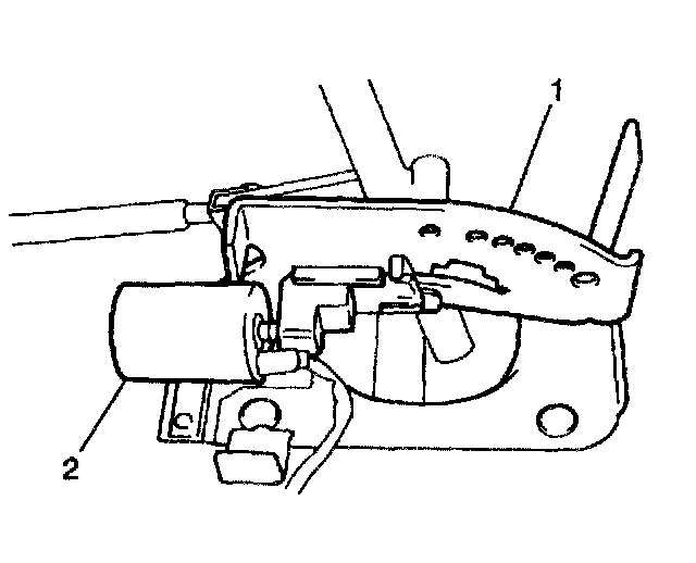
7. Remove the 2 retaining screws and the shift lock solenoid (2) from the selector lever housing (1).
INSTALLATION PROCEDURE
1. Move the selector lever to the P position.
2. Apply lithium grease GM P/N 1051344 to the upper and the lower edges of the solenoid lock plate at position 3 as shown in the figure.
3. Install the shift lock solenoid to the selector lever housing. Secure with 2 retaining screws (2). Do NOT tighten fully.
4. Install the shift lock solenoid electrical connector under the carpet.
5. Adjust the shift lock solenoid position so that the solenoid will operate in the manner described below.
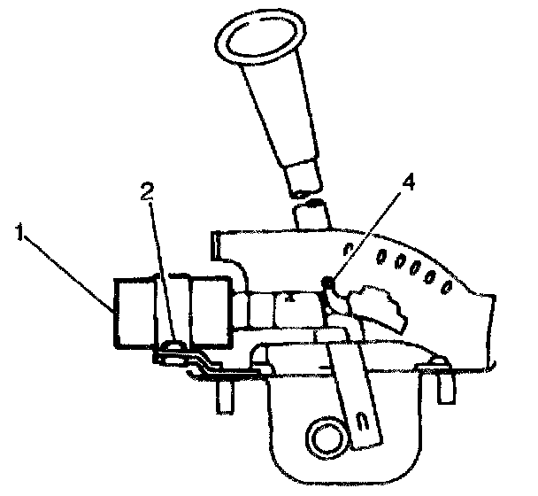
6. When the ignition switch is turned ON, and the brake pedal is depressed, the solenoid (1) is actuated.
IMPORTANT: When the ignition switch is turned OFF the solenoid (1) is NOT actuated.
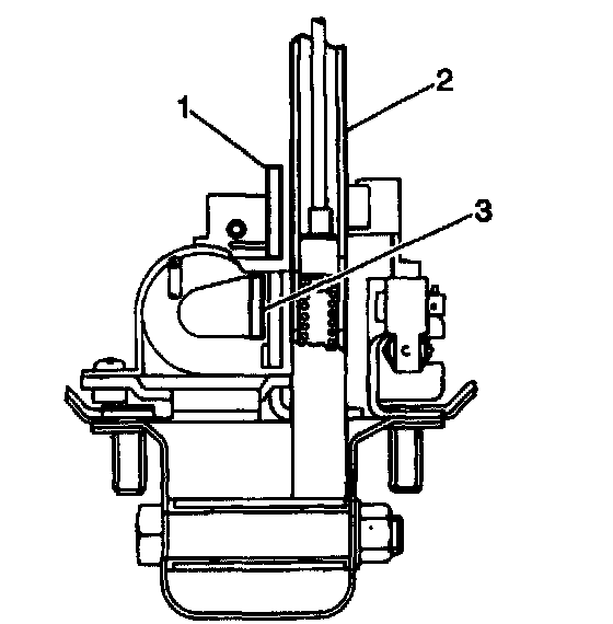
7. Allow no clearance between the solenoid lock plate (3) and the selector lever housing guide plate (1).
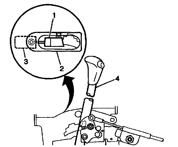
8. If the manual override (1) is enabled with the ignition switch in the OFF position, you can move the selector lever (4) to any range or position.
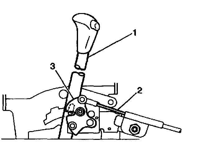
9. Tighten the shift lock solenoid retaining screws completely. Make sure the selector level (1) locks in the P position and cannot be shifted out of the P position to any other range or position.
10. Lower the cover onto the selector lever.
11. Slide the cover and the upper cover onto the selector lever. Secure the covers with 4 screws.
12. Install the console into the vehicle. Secure the console with 4 screws.
13. Install the selector lever knob to the selector lever. Secure with 2 screws.
14. Connect the negative (-) battery cable.