Refinishing Rotors
^ Tools Required- J 37704 Disc Brake Lathe
Notice: Do not refinish parking brake drum surface of rotor. Refinishing will result in reduced performance of parking brake.
The following two procedures are recommended and achieve adequate results using two different off-vehicle disc brake lathes. If any other lathe is used, follow that lathe's instructions and recommendations:
Ammco Brake Lathe(r)
Refer to the manufacturer's instructions for all initial setup and cutting procedures.
Accu Turn Brake Lathe(r)
GM Dealer Equipment (One Cut Refinishing Procedure)
Refer to the manufacturer's instructions for all initial setup and cutting procedures.
Nondirectional Finishing
Ensure that the rotor surface is nondirectional by dressing the rotor surfaces with one of the following sanding disc tools (or equivalent) using 120 grit aluminum oxide sandpaper:
^ Ammco(r) 8750 Safe Swirl Disc Rotor Grinder
^ Accu Turns 433170 Non-Directional Swirl Finisher
Use the following procedure for nondirectional finishing:
1. Sand each rotor surface with moderate pressure for a minimum of 60 seconds.
If the brake lathe is not equipped with an adequate nondirectional finishing tool, use a sanding block with 150 grit aluminum oxide sandpaper.
2. With the rotor turning at the equipment manufacturer's highest recommended cutting speed, sand each rotor surface for a minimum of 60 seconds using moderate pressure.
3. After the rotor has been sanded, clean each surface with denatured alcohol or a suitable brake cleaner.
The finished rotor surface should be as close as possible to that of a new rotor. Failure to obtain the best possible rotor finish may affect braking performance.
Rotor Mounting Adapter
^ Tools Required
- J 39144 Brake Rotor Mounting Adapter
Notice: Whenever the brake rotor has been separated from the wheel bearing flange, clean any rust or foreign material from the mating surface of the rotor and flange with the J 42450 hub cleaning kit. Failure to do this may result in increased lateral runout of the rotor and brake pulsation.
1. Inspect all the mounting hardware for the following conditions:
^ Rust
^ Nicks
^ Dirt
^ Abnormal Wear
Ensure that all components are clean and in good condition.
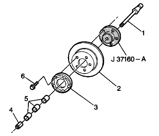
2. Inspect the rotor (2). Ensure that the mounting surface is clean and free of nicks.
3. Measure the lateral runout. Refer to Brake Rotor Lateral Runout Check.
4. Measure the thickness variation. Refer to Brake Rotor Tolerance.
5. Mount the J 39144 on the spindle arbor. Use a suitable combination of spacers (5) or collets in order to tighten the J 39144 to the arbor. Whenever you use lathes with a 7/8 inch spindle arbor, use an adapter sleeve with the J 39144. Do not use an adapter sleeve with lathes using a 1 inch spindle arbor.
6. Mount the rotor (2) onto the J 39144.
Notice: Refer to Fastener Notice in Service Precautions.
7. Mount the clamp plate (3) and five nuts (6). You may install and remove the rotor (2) while the J39144 is mounted on the machine spindle.
^ Tighten the nuts in a cross pattern to 34 Nm (25 ft. lbs.).
8. Install a silencer band on to the rotor (2).
9. Use the following procedure in order to verify correct installation of the rotor:
9.1. Bring the tool bit up and touch off when the machine is running.
9.2. Stop the machine and check the witness mark.
If the mark extends three quarters of the way around, the rotor is mounted properly.
10. If the rotor is mounted properly, continue with normal methods in order to resurface the rotor.
11. If the witness mark does not extend three quarters of the way around, repeat Steps 1 through 9.