Drive Belt - Tension Specifications, Checking/Adjusting
83porsche03Subject:
Drive Belts
Part Identifier N/A
Applies To
944
(Supersedes Product Circular, Grp. 13, No. 82-02)
Group
13
Key Points
^ Tension specifications
^ Checking/adjusting procedures
C
Number
83-01
March 15, 1983
Special tool 9201 must be used for testing the tightness of poly-rib and toothed bolts. Values required are as given in following table:
Note This information supersedes any previously published material on the same subject.
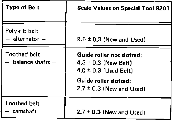
Belt Tension Specifications
Alternator/Compressor Belt, checking/adjusting
- prepare tool 9201 for testing. Hold tool as shown. Pull out lockpin, allowing gauge slide to drop so tool can be installed on belt without tension.
- move "tell tail" counterclockwise to "0" position on gauge.
- slide tool carefully onto belt. Push up on measuring slide until lockpin is heard to engage. Pull out lockpin and remove gauge. Read tension value by noting position of "tell-tale" pointer.
Note Full surface of gauge feet must rest on flat surface of belt. The tool should neither be turned nor moved on the belt during test.
- to adjust belt tension, slightly loosen bolts at either end of adjusting rod.
- loosen locknuts on adjusting rod and turn rod to obtain correct tightness of belt.
- tighten locknuts and bolts.
Balance shafts drive belt, checking/adjusting
Note Only check and adjust drive belt tightness on a cold engine (ambient temperature approx. 20~C)
- remove splash guard under engine
- remove poly-rib alternator/compressor belt
- remove belt cover bolts and loosen breather hose clamp at top cover. Take off toothed belt covers (upper and lower).
- loosen locking nut on guide roller without slot (older type) and turn eccentric so it is no longer preloading the toothed belt.
- loosen locking nut on guide roller with slot (new type) and slide roller away from belt so that it is no longer tensioning the belt.
- remove plug from mount for distributor cap.
- turn crankshaft clockwise until TDC mark on camshaft sprocket is aligned with cast mark.
- also check that scribe mark on flywheel is visible opposite TDC cast marking on clutch housing.
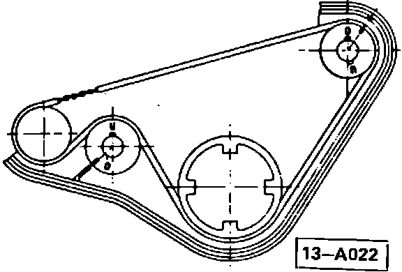
- check that balance-shaft sprocket marks are aligned with marks on rear toothed belt cover.
- prepare tool 9201 for testing (as described on page 1). Make sure "tell-tail" is set to zero.
- slide gauge carefully onto belt. Push measuring slide until lockpin is heard to engage. Pull out lockpin and remove gauge. Read tension value at position of "tell-tail" pointer.
- to adjust belt tension, loosen locking nut from eccentric tensioning roller. Turn roller clockwise to tighten or counter-clockwise to loosen. Tighten nut to specified tightening torque
^ tightening torque: 45 N-m (33 ft.lbs.)
- adjust guide roller after adjustment of belt tension to visually preload belt by 1.0 to 2.0 mm as follows:
Roller without slot - -
- turn guide roller counterclockwise to preload belt; then tighten nut to 45 N-m (33 ft.lbs.)
Roller with slot - -
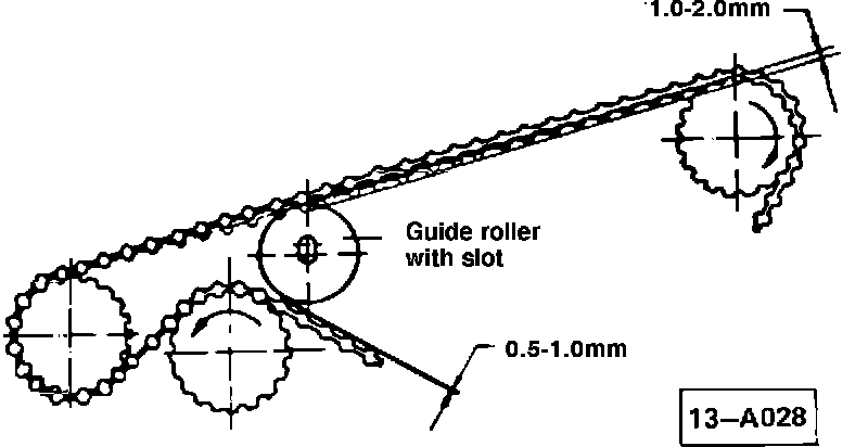
- maintain 0.5 to 1.0 mm clearance between guide roller and lower balance shaft (use tool 9207 or a 0.5 mm feeler gauge), and push guide roller against belt until proper preload is achieved; then tighten nut to 45 N-m (33 ft.lbs.)
- if the adjusting distance is not sufficient, turn guide roller 180~ and repeat the adjustment
- reinstall belt covers
- reinstall and adjust alternator/compressor belt
- reinstall splash guard
Camshaft drive belt, checking/adjusting
^ engine must be cold (ambient 20~C approx.)
CAUTION
Follow work sequence exactly. Otherwise, erroneous results will be obtained.
Work sequence
- remove splash guard, belt covers and alternator/ compressor belt.
- turn crankshaft clockwise while observing condition of drive belt. Replace, if damaged or excessively worn.
- remove plug from mount for distributor cap
- turn crankshaft clockwise until TDC mark on camshaft sprocket is aligned with cast mark on mounting for distributor cap.
- check that TDC marks on flywheel and clutch housing are approximately aligned
CAUTION
Do not take drive-belt tension reading with belt in this position.
- NOW, turn crankshaft counterclockwise by about 10~ (approx. 1.5 teeth on camshaft sprocket). THIS STEP IS MANDATORY. Otherwise, tension measurement will be invalid. ENGINE DAMAGE CAN RESULT.
- prepare special gauge tool 9201 for testing (as described on page 1)
- move the "tell tail" counterclockwise to the "0" position on the gauge
- slide tool 9201 carefully onto the drive belt. Push down on measuring slide slowly until the lockpin can be heard to engage. Pull out on lockpin and carefully remove gauge
- take reading value at position of the "tell-tail" pointer
Note The gauge tool should neither be turned nor moved on the belt during test.
- to adjust belt tension, loosen locking nut and turn tensioning roller counterclockwise to tighten or clockwise to loosen
- tighten locking nut to specified tightening torque while counterholding
^ tightening torque: 45 N-m (33 ft.lbs.)
- turn engine two revolutions clockwise and again align TDC mark on camshaft sprocket with cast mark on mounting for distributor cap. Turn engine counter-clockwise from this position by approx. 10~ on crankshaft (1-1/2 teeth on camshaft sprocket)
- recheck and, if necessary, correct drive belt tension
- replace belt covers, reinstall and tension alternator/compressor belt, reinstall splash guard
Note Checking, and if necessary, adjusting camshaft drive-belt tightness as part of 500-2000 mile inspection, and at 15,000 miles, is recommended
Time Allowance:
^ Alternator belt check and adjust - 25 T.U.
^ Balance-shaft belt checking only - 50 T.U.
^ Camshaft belt check/adjust - 80 T.U.*
^ Balance-shaft belt check/adjust - 90 T.U.*
^ Adjust both camshaft and balance shaft belts
- 110 T.U.*
* includes alternator-belt adjustment