Vehicles Equipped With Sanden Compressor
1. Check the operation of the A/C system as follows:^ Carry out an A/C performance test. For 9000 models see page 194 in Service Manual Section 8:3 Air conditioning or page 854-44 in Service Manual Section 8:3 "Heating and ventilation system, air conditioning system" for the 900.
^ Carry out leak detection procedure.
Repair any system faults or damage in conjunction with conversion when the A/C system has been purged of refrigerant.
2. Purge the A/C system of refrigerant. Note the amount of compressor oil that is drained.
3. Repair any damage to the A/C system.
4. Depending upon model:
9000: Remove the cover over the false bulkhead space.
900: Remove the cover over the evaporator.
5. All models except 9000 M92:
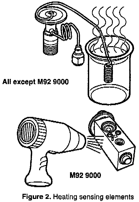
Remove the expansion valve's sensing element and heat it in hot water.
9000 M92:
Heat the expansion valve's sensing element using a hot-air gun.
See Diagram (figure 6) for hose routing instructions as indicated below.
6. Connect the pressure gauge stand's blue hose to the service nipple of the flushing kit.
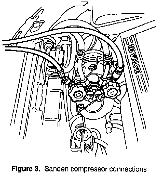
7. Remove the Schrader valves and Schrader openers in the A/C system and on the equipment so that a free and unobstructed flow is obtained during the flushing process.
8. Connect one end of the blue low-pressure hose to the blue low-pressure valve on the purging station's tank.
9. Connect the other end of the blue low-pressure hose to the high-pressure side of the compressor.
10. Remove the compressors oil filler plug and fit the adapter supplied in the set.
11. Connect one end of the red high-pressure hose to the suction side of the flushing unit.
12. Connect the other end of the red high-pressure hose to the compressor's oil filling connection.
13. Make sure that the valve on the red high-pressure hose is open.
14. Open both valves on the tank and start the purging station.
15. Open the blue low-pressure valve and fill with refrigerant (liquid).
16. When the oil is drained, foam and streaks of oil will be visible in the flushing kit's sight glass. Close the blue valve on the low-pressure hose when the sight glass is at least half full of liquid. Open the valve again when the sight glass is empty or when the pressure has dropped by about 1 bar.
Repeat this procedure until no more bubbles are visible in the sight glass. Rotate the compressor's swash plate a couple of turns during the flushing process.
17. Close the blue valve on the hose when the A/C system has been purged of oil (after about 45 minutes).
18. Drain off the compressor oil from the purging station and note the amount. Check that at least 90% of the total system volume of oil has been removed.
19. Refit the expansion valve's sensing element.
20. Change the receiver drier for the one supplied in the kit.
21. Depending upon model:
9000:
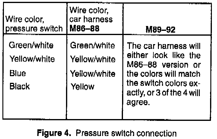
Fit the three-stage pressure switch supplied in the set on the new receiver. Refer to Table for correct wire connections.
900:
Transfer the pressure switch from the old receiver to the new one.
22. Refit the Schrader valves that will be needed for the service valves that are to be fitted.
23. Refit other components that have been removed.
24. Fill the compressor crankcase with the specially developed retrofit compressor oil. This oil is supplied in the spare pans kits.
9000: 135 ml
900: 170 ml
25. Screw the oil filler plug back in the compressor.
26. Install the new service valves supplied in the kit. The larger one is for the high-pressure side; the smaller one for the low-pressure side.
27. Connect the equipment for R134a. Evacuate the A/C system and fill it with R134a refrigerant.
9000: 950 grams
900: 900 grams
28. Remove the existing A/C labels and stick the "Retrofit" labels on in the same places. Labels are supplied in the kit.
29. Carry out leak detection and performance testing as described in the service manual.